TM 5-3805-262-20
INSPECTION (SHEET 3 OF 3)
(7)
(8)
(9)
(10)
(11)
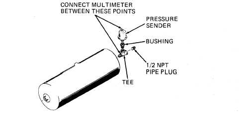
I n s t a l l t e e , b u s h i n g , p r e s s u r e s e n d e r , a n d 1 / 2 N P T p i p e p l u g i n a i r r e s-
e r v o i r a s s h o w n b e l o w . D o n ’ t r e m o v e p a r t s i n s t a l l e d i n s t e p ( 6 ) a b o v e e x -
cept 1/2 NPT pipe plug. Connect multimeter between points shown below.
Multimeter should indicate between zero to 6 ohms. If not, replace pres-
sure sender.
Ensure that drain valve in air reservoir is closed. Connect a source of
compressed air to tee in which safety valve is installed and slowly in-
crease air pressure applied to air reservoir while watching multimeter.
With zero psi applied , multimeter should indicate zero to 6 ohms; at 30
psi pressure multimeter should indicate 17 to 27 ohms; at 65 psi, 40 to
50 ohms; at 90 psi, 60 to 70 ohms; and at 120 psi, 80 to 96 ohms. Discon-
nect compressed air source and open drain valve to release air pressure,
Replace pressure sender if any of the above indications are not obtained.
R e m o v e a l l p a r t s i n s t a l l e d i n a i r r e s e r v o i r.
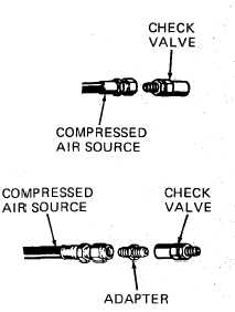
Connect a source of compressed air to check valve as
shown. Apply a maximum of 50 psi pressure and check
that air is vented through check valve. If not, re-
place check valve. Disconnect compressed air source.
Install adapter in check valve and connect a
source of compressed air to adapter as shown.
Apply a maximum of 100 psi pressure and check
that air is not vented through check valve. If
air is vented, check valve is defective and must
7-61