TM 5-3805-262-34
DISASSEMBLY (SHEET 1 OF 4)
a.
Remove four capscrews (1).
b.
Scribe alinement marks on slip ring end frame and drive end frame.
Use extreme care not to touch stator (3) winding when inserting screw-
driver blades and prying end frames apart.
Do not use hammer to drive
frames apart.
c.
Using two screwdrivers,
work evenly around circumference of end frames and
separate slip ring end frame from drive
end frame. Set assembled drive end
frame aside.
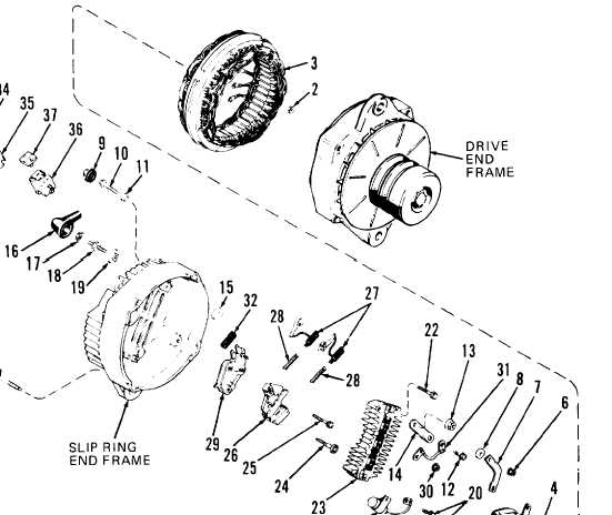
LEGEND
1. Capscrews (4)
2. Nuts (3)
3. Stator
4. Capscrew
5. Diode trio
6. Nut
7. Connector
8. Insulator
9. Cap
10. Relay terminal
11. Insulator
12. Capscrew
13. Nut
14. Connector
15. Insulator
16. Boot
17. Nut
18. Battery terminal
19. Insulator
20. Capscrews (2)
21. Capacitor
22, Capscrews (2)
23. Rectifier bridge
24. Capscrew
25.
26.
27.
28.
29.
30.
31.
Capscrew
Brush holder
32. Insulator
Brushes (2)
33. Capscrew
Springs (2)
34. Lock washer
Voltage regulator
35. Bracket
Nut
36. Connector
Electrical lead
37. Cap
3-203