TM 5-3805-262-34
DISASSEMBLY (SHEET 2 OF 40)
d.
e.
f.
g.
h.
i.
j.
k.
l.
m.
n.
o.
p.
q.
r.
s.
t.
u.
v.
Remove three nuts (2) securing stator (3) leads to rectifier bridge (23).
Disconnect three stator (3) leads from
rectifier bridge (23) studs.
Carefully pull stator (3) from slip ring
end frame.
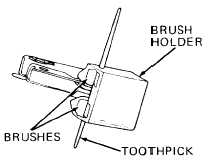
Push brushes (27) into brush holder
(26), then insert a toothpick through
holes in brush holder and brushes to
hold brushes in position.
Remove capscrew (4) and diode trio (5).
Remove nut (6), connector (7), and insulator (8).
Remove cap (9) , relay terminal (10), and insulator (11).
Remove capscrew (12) securing electrical lead (31) to rectifier bridge (23).
Remove nut (13), connector (14), and insulator (15) from battery terminal
(18).
Remove boot (16), nut (17), battery terminal (18), and insulator (19).
Remove two capscrews (20) and capacitor (21).
Remove two capscrews (22) and rectifier bridge (23).
Remove capscrews (24 and 25) and brush holder (26).
Remove toothpick from brush holder (26), pull two brushes (27)
(28), then pull two springs (28) from brush holder (26).
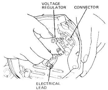
Pull voltage regulator (29) with
electrical lead (31) from connec-
tor (36).
Remove nut (30) and disconnect
electrical lead (31) from voltage
regulator (29).
Pull insulator (32) from voltage
regulator (29) terminals.
Remove capscrew (33), lock washer
(34), and bracket ( 35).
Remove connector (36) from slip
ring end frame, then pull cap (37)
from connector (36).
from springs
3-205


