
TM 5-3805-290-23-1
THEORY OF OPERATION - CONTINUED
0003 00
FUEL SYSTEM - CONTINUED
a.
Delivery.
(1)
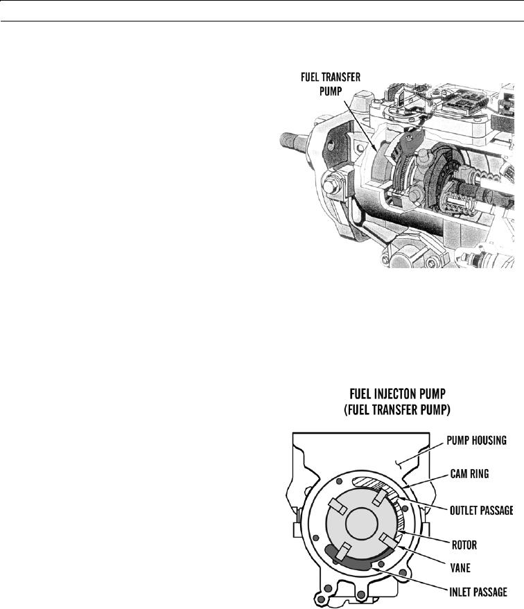
Fuel is supplied by priming pump. Fuel
enters transfer pump of fuel injection
pump. Fuel transfer pump is a vane type
pump driven by fuel injection pump
shaft. Pump supplies a constant amount
of fuel to interior of fuel injection pump.
Revolution of transfer pump is directly
related to speed of fuel injection pump
shaft.
427-B1507
(2)
Rotor rotates inside cam ring. Cam ring is firmly attached to pump housing. Vanes are pressed against cam
ring by centrifugal force. Fuel flows through an inlet passage into recess in pump housing.
(3)
Eccentric position of rotor is relative to cam ring. A volume is created between: vanes, rotor, and cam ring.
Fuel is transported by eccentric position relative to rotor and outlet passage. Fuel is transferred through
outlet passage into distributor plunger. Volume of fuel is reduced between inlet passage and outlet passage.
This creates pressure before delivery to distributor plunger.
(4)
Fuel quantity increases as speed of
engine increases. Increased engine speed
increases fuel delivery pressure. Pressure
inside fuel injection pump is limited by
pressure regulator. Pressure regulator
controls fuel pressure. Fuel forces valve
spring open and flows back into inlet
passage from inside of fuel injection
pump.
427-B1516
0003 00-8