
TM 5-3805-290-23-1
THEORY OF OPERATION - CONTINUED
0003 00
FUEL SYSTEM - CONTINUED
(1)
Injection pump ECU is mounted on top of pump. ECU has a connection to engine ECM and a connection
to speed/timing sensor. ECU has a connection for two solenoid valves. ECM functions as a control com-
puter. ECU calculates optimal parameters from ECM data. Fuel solenoid actuates valve accordingly.
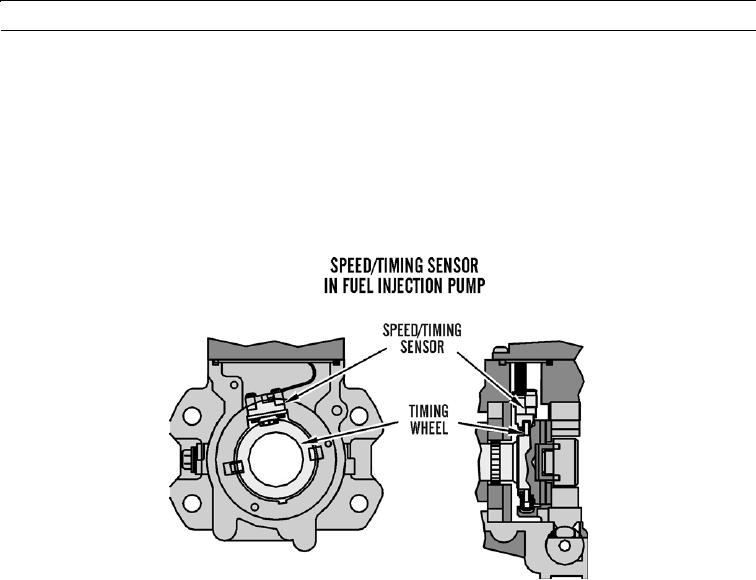
(2)
Speed/timing sensor in fuel injection pump determines precise angular position and speed of fuel injection
pump shaft. Timing wheel is permanently connected to fuel injection pump shaft. Speed/timing sensor gets
information from timing wheel. Sensor then sends electrical impulses to ECU. ECU also uses information
to determine average and momentary pump speed.
(3)
Speed/timing signal sensor is constant.
427-B1524
0003 00-13