
TM 5-3805-290-23-1
THEORY OF OPERATION - CONTINUED
0003 00
HYDRAULIC SYSTEM - CONTINUED
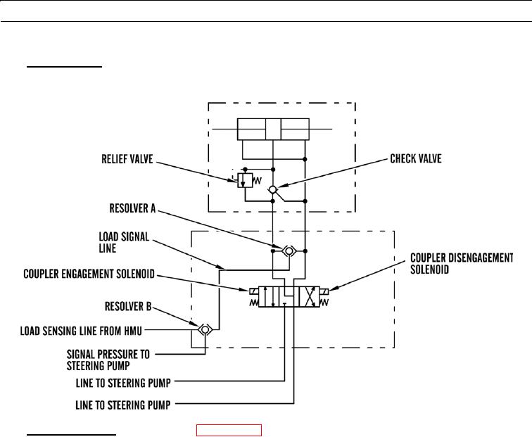
Coupler Control. Engagement solenoid is energized in order to engage coupler pins. Disengagement solenoid is ener-
8.
gized in order to disengage coupler pins. Load signal flows to resolver (A). Resolver (A) shifts. Load signal flows to
resolver (B). Resolver shifts (B). Load signal flows to pump. Pump flow increases.
427-B1764
Main Control Valve. Refer to schematic (WP 0210 00).
9.
a.
Oil flows from piston pump, through line from pump, to main control valve. Control valves in main control valve
control flow of hydraulic oil from pump to cylinders and work tools. Control valves send signal oil back to pres-
sure and flow compensator valve through line to pressure and flow compensator valve.
b.
Hydraulic oil flows into main control valve. Line from pump to main control valve carries pressure oil from piston
pump to all control valves. Line from main control valve to tank carries return oil away from control valves to
tank. Control valves in main control valve are load sensing valves. Pressure compensator in each control valve
determines function with highest load. Highest load is applied to all pressure compensators. Also, highest load is
sent to pump. This is signal pressure.
c.
Pump uses signal pressure to determine amount of required flow. If pump flow is not sufficient for all of functions,
flow of hydraulic oil to all functions is reduced proportionally.
d.
Bank valve contains a signal limiter valve, a signal drain line flow control valve, and throttle pin. Signal limiter
valve limits signal oil pressure that flows to pressure and flow compensator valve on piston pump to 3,450 psi
(23,787 kPa). When control valves return to HOLD position, flow control valve for pilot drain valve allows signal
oil to flow to tank. Throttle pin dampens flow of signal oil to pressure and flow compensator valve to control
upstroking and destroking speed of pump. Signal limiter valve, signal drain valve flow control valve, and throttle
pin operate for all control valves in main control valve.
e.
Spools are controlled by pilot oil from pilot valves.
0003 00-164