
TM 5-3805-290-23-1
ENGINE TESTS, INSPECTIONS, AND ADJUSTMENTS - CONTINUED
0010 00
FINDING TOP-CENTER POSITION FOR NO. 1 PISTON - CONTINUED
2.
Remove valve mechanism cover (WP 0024 00).
3.
Rotate crankshaft clockwise when facing front of
engine. Rotate crankshaft until pushrod for inlet valve
of rear cylinder begins to tighten.
427-B2078
4.
Rotate crankshaft further clockwise by 1/8 turn. Insert lever between rocker lever and valve spring cap of No. 1 inlet
valve. Open inlet valve. Position spacer approximately 0.2 in. (5.0 mm) thick between valve stem and rocker lever.
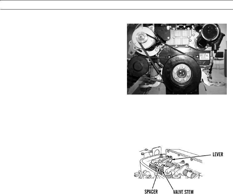
5.
Slowly rotate crankshaft counterclockwise until piston makes contact with open valve. Make temporary mark (2) on
damper or pulley to align with tip of pointer.
6.
Rotate crankshaft clockwise by one or two degrees.
Remove spacer between valve stem and rocker lever.
Rotate crankshaft counterclockwise 1/4 turn. Position
spacer that is approximately 0.2 in. (5.0 mm) thick
between valve stem and rocker lever of No. 1 inlet
valve.
427-B0511-2
7.
Slowly rotate crankshaft clockwise until piston makes contact with open valve. Make another temporary mark (2) on
damper or pulley to align with tip of pointer (1).
8.
Make temporary mark (2) at center point between two marks on damper or pulley. Remove other two marks. Rotate
crankshaft counterclockwise 1/8 turn. Remove spacer between valve stem and rocker lever.
0010 00-6