
TM 5-3805-290-23-1
FUEL SYSTEM TESTS, INSPECTIONS, AND ADJUSTMENTS - CONTINUED
0011 00
N OT E
For a better understanding of each system, review the appropriate section in Theory of Operation (WP 0003
0011 00
AIR IN FUEL TEST
1.
Inspect fuel system for leaks.
2.
Ensure fuel line fittings are properly tightened (WP 0035 00 and WP 0038 00).
3.
Check fuel level in fuel tank (TM 5-3805-290-10).
N OT E
Air can enter fuel system on suction side between fuel transfer pump and fuel tank.
When possible, install sight gage in straight section of fuel line that is at least 12 in. (30.5 cm) long. DO
NOT install sight gage near the following fittings which create turbulence: elbows, relief valves, and
check valves.
4.
Install fluid filter (sight gage tool) in fuel return line.
5.
Observe fuel flow during engine cranking. Check for air bubbles in fuel. If there is no fuel in sight gage, prime fuel sys-
tem (WP 0029 00).
6.
If engine starts, check for air in fuel at varying engine speeds. If possible, operate engine under conditions which have
been noted to have problems.
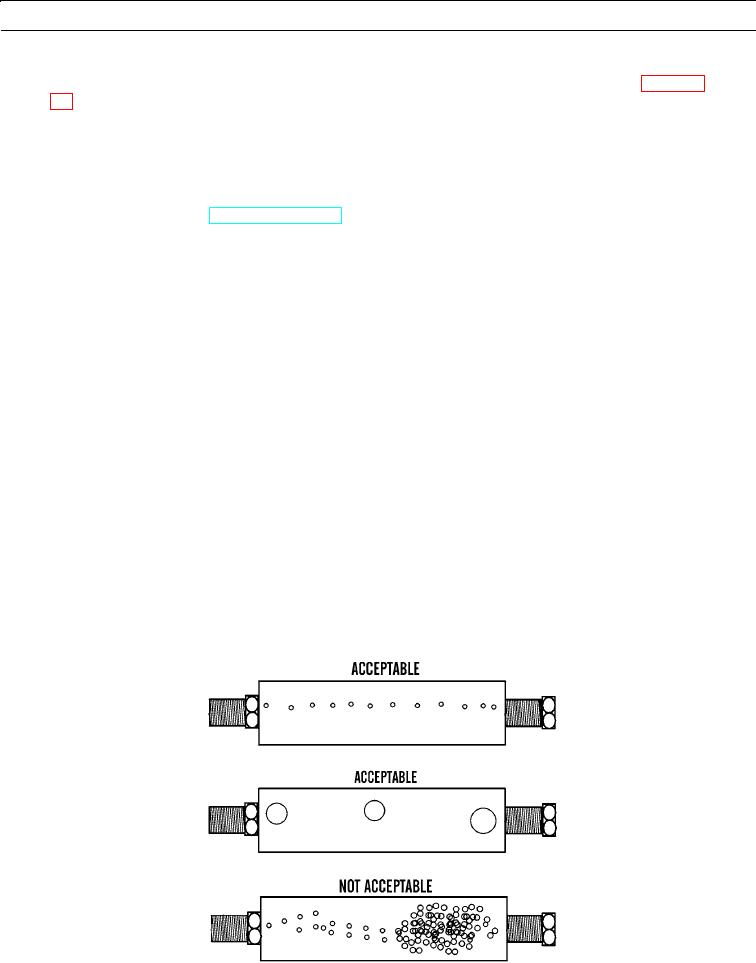
N OT E
Steady stream of small bubbles with diameter of approximately 0.063 in. (1.60 mm) is acceptable
amount of air in fuel.
Bubbles with diameter of approximately 0.250 in. (6.35 mm) are also acceptable if there is a two- to
three-second interval between bubbles.
Excessive air bubbles in fuel are not acceptable.
7.
Refer to illustration below for acceptable amounts of air in fuel.
427-B0651