TM 5-3805-290-23-1
ELECTRICAL SYSTEM TESTS, INSPECTIONS, AND ADJUSTMENTS - CONTINUED
0013 00
CAN DATA LINK CIRCUIT TEST - CONTINUED
2.
Inspect electrical connectors and wiring. Refer to Electrical Connectors Inspection (WP 0022 00).
a.
Turn engine start switch to OFF position (TM 5-3805-290-10).
b.
Disconnect and check connectors and wiring for these problems: damage, corrosion, abrasion, and incorrect
attachment (WP 0169 00 thru WP 0175 00).
c.
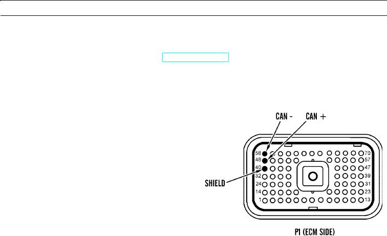
Pay close attention to these areas (harness side and ECM side):
(1)
P1:48 CAN +
(2)
P1:58 CAN -
(3)
P40:2 CAN +
(4)
P40:1 CAN -
427-B0677
d.
Expected Results. Connectors and wiring should be free of damage, corrosion, abrasion, and incorrect attachment.
(1)
If connectors and wires are OK, reconnect all connectors and proceed to step 3.
(2)
If connectors and wires are NOT OK:
(a) Replace connectors causing problem.
(b) Ensure all seals are properly placed and all connectors are secured correctly.
(c) Verify repair eliminates problem.
(d) If problem is still not corrected, replace wiring harness in question (WP 0169 00 thru WP 0175 00).
(e) If problem still exists, go to step 3.
3.
Check CAN data link between ECM P40 and fuel injection pump control unit connector for open circuit.
a.
Disconnect P1 from ECM (WP 0053 00).
N OT E
DO NOT disconnect P40 Fuel Pump Connector.
b.
Measure resistance between terminal P1:48 and terminal P1:58.
c.
Expected Results. Readings should be between 100 and 132 Ohms.
(1)
If reading is OK, proceed to step 4.
(2)
If reading is NOT OK, an open circuit exists in harness between P1 ECM connector and control unit for
fuel injection pump. Replace engine wiring harness (WP 0170 00).
0013 00-12

