
TM 5-3805-290-23-1
ELECTRICAL SYSTEM TESTS, INSPECTIONS, AND ADJUSTMENTS - CONTINUED
0013 00
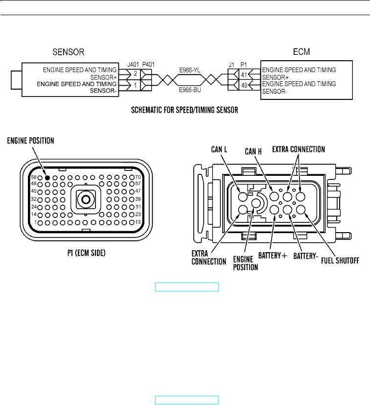
ENGINE SPEED/TIMING SENSOR CIRCUIT TEST - CONTINUED
427-B0710
427-B0713
427-B1537
a.
Turn engine start switch to OFF position (TM 5-3805-290-10).
b.
Disconnect P1 ECM connector and P40 fuel injection pump connector (WP 0053 00 and WP 0164 00).
c.
Measure resistance from terminal 59 engine speed/timing sensor at ECM to terminal 8 engine speed/timing sensor
of P40 fuel injection pump connector. Resistance should be less than 2 Ohms.
d.
Reconnect all connectors.
e.
Expected Results. Readings agree with values listed in step c.
(1)
If results are OK, ECM does not operate properly. Perform this repair on suspect ECM:
Replace engine ECM (WP 0053 00). Verify repair eliminates problem.
(2)
If results are NOT OK, readings are higher than 2 Ohms. Proceed to step 6.
6.
Check continuity of cables from ECM to fuel injection pump.
a.
Turn engine start switch to OFF position (TM 5-3805-290-10).
b.
Disconnect J1/P1ECM connector and J40/P40 fuel injection pump connector (WP 0053 00 and WP 0164 00).
0013 00-44