
TM 5-3805-290-23-1
HYDRAULIC SYSTEM TESTS, INSPECTIONS, AND ADJUSTMENTS - CONTINUED
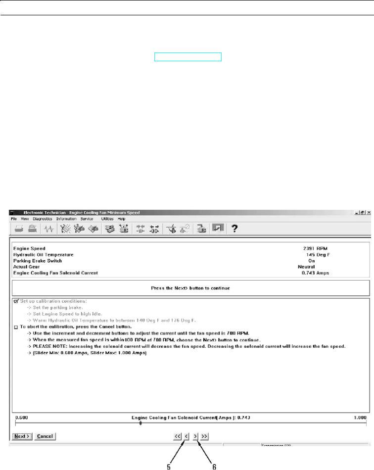
0017 00
FAN SPEED CALIBRATION - CONTINUED
c.
Perform these procedures to obtain conditions for setup:
(1)
Ensure parking brake is engaged (TM 5-3805-290-10).
(2)
Run engine at high idle with throttle lock.
(3)
Monitor hydraulic oil temperature with MSD screen and stall hydraulic function to increase hydraulic oil
temperature. Stall hydraulic function by moving function to end of travel.
d.
When conditions for setup are obtained, press "Next" button to start calibration. If conditions for setup are not cor-
rect, condition that is not correct will be displayed in middle display area. Calibration will not start. When condi-
tions are correct, press "Next" button to start fan speed calibration.
N OT E
When minimum fan speed is being calibrated, maximum signal will be sent to hydraulic demand fan sole-
noid to obtain minimum fan speed.
Cancel calibration at any time by pressing "Cancel" button.
427-B0807
0017 00-25