
TM 5-3805-290-23-2
ELECTRICAL GENERAL MAINTENANCE INSTRUCTIONS - CONTINUED
0022 00
CONNECTOR REPAIR
0022 00
N OT E
Perform the following steps for each wire of connector.
Tag wires to aid in installation.
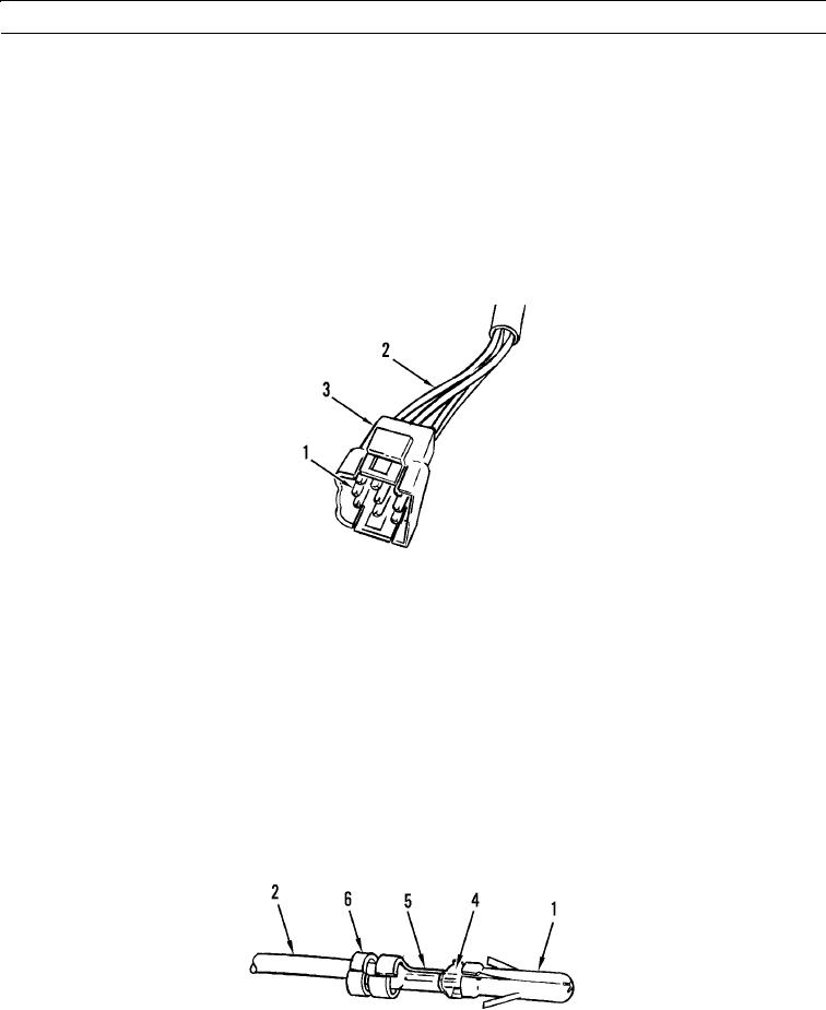
1.
Using pin removal tool, position tool over pin (1) and push inward to retract two barbs of pin.
2.
Remove wire (2) with pin (1) attached, from rear of connector (3).
3.
If damaged, remove pin (1) from wire (2) by cutting through wire just behind pin.
427-B1920
N OT E
Perform steps 4 thru 6 only if pin was removed.
4.
Using wire stripping tool, strip insulation from wire (2) to expose proper length of metal strands (4).
5.
Using crimping tool, securely crimp tabs (5) of pin (1) over metal strands (4) of wire (2).
N OT E
The other two pin tabs may need to be crimped slightly to enter connector.
6.
Using crimping tool, crimp tabs (6) at rear of pin (1) over insulation of wire (2).
427-B1921
7.
Push pin (1) into rear of connector (3) until fully seated.
0022 00-4