
TM 5-3805-290-23-2
KICKOUT SENSORS REPLACEMENT - CONTINUED
0057 00
RETURN TO CARRY KICKOUT SENSOR REMOVAL
0057 00
N OT E
The following procedures remove and install the return to carry kickout sensor. The procedures for remov-
ing and installing the lift kickout sensor are identical.
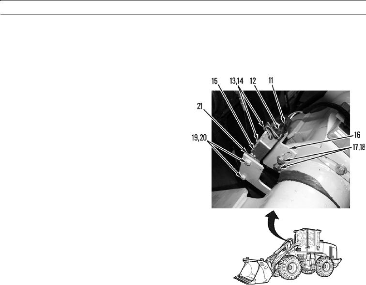
1.
Cut and discard tiedown strap (11).
2.
Disconnect wiring harness (12) from kickout sensor
(15).
3.
Remove two bolts (13), washers (14), and kickout sen-
sor (15) from bracket (16).
4.
Remove two bolts (17), washers (18), and bracket (16)
from machine.
5.
Remove two bolts (19), washers (20), and magnet (21)
from machine.
427-B0226
RETURN TO CARRY KICKOUT SENSOR INSTALLATION
1.
Install magnet (21), two washers (20), and bolts (19) on machine.
2.
Install bracket (16), two washers (18), and bolts (17) on machine.
3.
Install kickout sensor (15), two washers (14), and bolts (13) on bracket (16).
4.
Connect wiring harness (12) to kickout sensor (15).
5.
Install new tiedown strap (11).
6.
Verify correct operation of lift and return to carry kickouts (TM 5-3805-290-10).
END OF WORK PACKAGE
0057 00-3/(0057 00-4 Blank)