
TM 5-3805-290-23-2
HYDRAULIC/TRANSMISSION OIL COOLER REPLACEMENT - CONTINUED
0089 00
INSTALLATION
WARN I N G
Use extreme caution when handling heavy parts. Provide adequate support and use assistance during pro-
cedure. Failure to follow this warning may result in injury to personnel.
N OT E
Hydraulic/transmission oil cooler assembly weighs 42 lb (19 kg).
Apply a thin coat of clean oil to all O-rings before installation.
1.
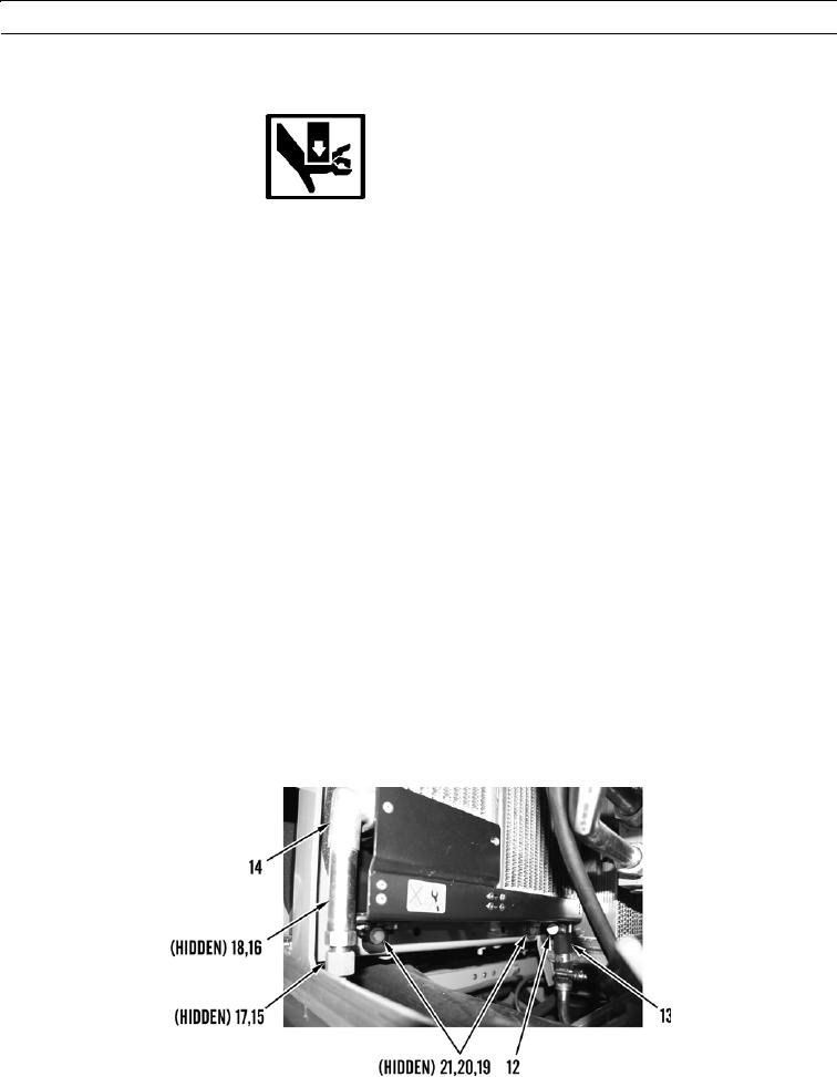
With assistance, position hydraulic/transmission oil cooler assembly (14) on machine.
2.
Install two bolts (30), four washers (29), and two nuts (28) on hydraulic/transmission oil cooler assembly (14).
3.
Install new O-ring (27) on fitting (25).
4.
Install fitting (25) on hydraulic/transmission oil cooler assembly (14).
5.
Install new O-ring (26) on fitting (24).
6.
Install fitting (25) on hydraulic/transmission oil cooler assembly (24).
7.
Connect hose (23) to hydraulic/transmission oil cooler assembly (14) and tighten clamp (22).
8.
Install two nuts (21), four washers (20), and two bolts (19) on hydraulic/transmission oil cooler assembly (14).
9.
Install new O-ring (18) on fitting (16).
10.
Install fitting (16) on hydraulic/transmission oil cooler assembly (14).
11.
Install new O-ring (17) on hose (15).
12.
Connect line (15) to fitting (16).
13.
Connect hose (13) on hydraulic/transmission oil cooler assembly (14) and tighten clamp (12).
427-B1847
0089 00-7