
TM 5-3805-290-23-2
DRIVE SHAFT MAINTENANCE - CONTINUED
0090 00
REAR DRIVE SHAFT INSTALLATION
N OT E
Bearing caps and yoke ends should be cleaned prior to assembly.
1.
With assistance, install rear drive shaft (6), two straps (2), and four bolts (1) in yoke (3). Tighten bolts to 50 10 lb-ft
(68 14 Nm).
2.
Install two straps (5) and four bolts (4) in yoke (7). Tighten bolts to 50 10 lb-ft (71 14 Nm).
WAR N I N G
Before operating equipment, secure the steering frame lock in the stowed position. DO NOT operate
machine with steering frame lock connected. Failure to lock steering frame lock into the stowed position
before operating can result in loss of steering and injury or death to personnel.
3.
Secure steering frame lock in stowed position (TM 5-3805-290-10).
4.
Operate machine at different speeds to verify correct operation (TM 5-3805-290-10).
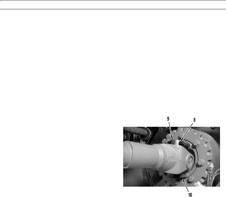
CENTER DRIVE SHAFT REMOVAL
N OT E
Center drive shaft is on a slip yoke.
Match mark shaft and yoke to
ensure correct installation.
1.
Remove four bolts (8) and two straps (9) from yoke
(10).
427-B0027
0090 00-3