
TM 5-3805-290-23-2
SERVICE BRAKE LINES AND FITTINGS REPLACEMENT - CONTINUED
0095 00
INSTALLATION
N OT E
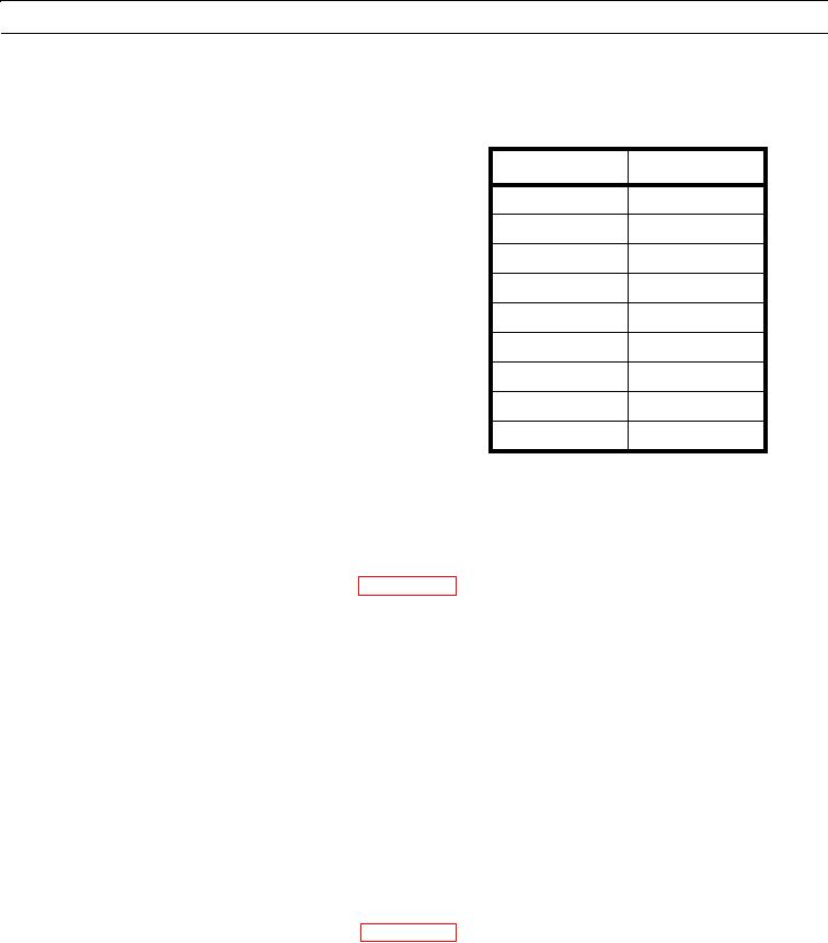
Table 2. Hose Installation.
Table 2 will refer you to the proper steps
for installation of each hose.
Hose
Step
4
38
5
34
12
27
13
27
14
24
20
20
28
11
36
7
48
1
N OT E
Apply a thin coat of clean oil to all O-rings before installation.
1.
Position hose (48) on machine and connect hose to manifold fitting (49).
2.
Connect hose (48) to service brake control valve (WP 0093 00).
3.
Install clamp (46) on hose (48).
4.
Install clamp (46), spacer (45), clamp (44), washer (43), bolt (42), and nut (41) on bracket (47).
5.
Install three new O-rings (40) on elbow (39).
6.
Install elbow (39) on front axle (37).
7.
Position hose (36) on machine and connect to elbow (39).
8.
Install three new O-rings (38) on T (33).
9.
Install T (33) on front axle (37).
10.
Connect hose (36) to T (33).
11.
Install sheath (35) on hose (28) and install two new tiedown straps (34) on sheath.
12.
Position hose (28) on machine and connect hose to T (33).
13.
Connect hose (28) to service brake control valve (WP 0093 00).
14.
Install grommet (31) and two clips (32) on hose (28).
15.
Install washer (30) and bolt (29) on machine.
16.
Install two clamps (27) on hose (28).
17.
Install two washers (26) and bolts (25) on machine.
0095 00-7