
TM 5-3805-290-23-2
SERVICE BRAKE LINES AND FITTINGS REPLACEMENT - CONTINUED
0095 00
N OT E
Tag hoses prior to removal to ensure correct installation.
Use a container to catch any fluid that may drain from hoses or system. Dispose of fluid IAW local policy and
ordinances. Ensure all spills are cleaned up.
REMOVAL
N OT E
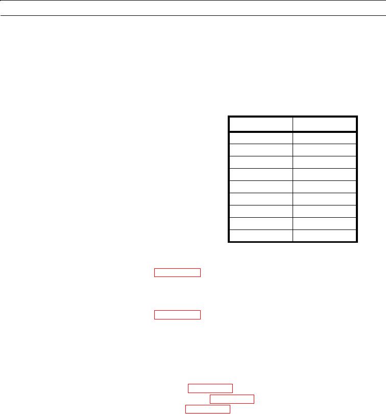
Table 1. Hose Removal.
Table 1 will refer you to the proper steps
for removal of each hose.
Hose
Step
4
1
5
1
12
11
13
11
14
11
20
19
28
25
36
32
48
38
1.
Remove bolt (1) and washer (2) from machine.
2.
Remove clamp (3) from hoses (4 and 5).
3.
Disconnect hose (4) from brake accumulator (WP 0096 00).
4.
Disconnect hose (4) from elbow (6) and remove hose from machine.
5.
Remove elbow (6) from brake/hydraulic fan pump (7).
6.
Remove two O-rings (8) from elbow (6). Discard O-rings.
7.
Disconnect hose (5) from brake accumulator (WP 0096 00).
8.
Disconnect hose (5) from elbow (9) and remove hose from machine.
9.
Remove elbow (9) from brake/hydraulic fan pump (7).
10.
Remove two O-rings (10) from elbow (9). Discard O-rings.
11.
Remove three tiedown straps (11) from hoses (12, 13, and 14). Discard tiedown straps.
12.
Remove two bolts (15) and washers (16) from machine.
13.
Remove two clips (17) from hoses (12 and 13).
14.
Disconnect hoses (12 and 13) from brake accumulators (WP 0096 00).
15.
Disconnect hoses (12 and 13) from service brake control valve (WP 0093 00) and remove hoses from machine.
16.
Disconnect hose (14) from service brake control valve (WP 0093 00).
17.
Remove tiedown strap (18) from hose (14). Discard tiedown strap.
18.
Disconnect hose (14) from T (19) and remove hose from machine.
19.
Disconnect hose (20) from T (19).
20.
Remove T (19) from rear axle (21).
21.
Remove three O-rings (22) from T (19). Discard O-rings.
22.
Disconnect hose (20) from T (23) and remove hose from machine.
23.
Remove T (23) from rear axle (21).
24.
Remove three O-rings (24) from T (23). Discard O-rings.
0095 00-3