
TM 5-3805-290-23-2
STEERING WHEEL REPLACEMENT - CONTINUED
0098 00
INSTALLATION
1.
Install knob (8), bolt (7), and cover (6) on steering wheel (2).
N OT E
Ensure splines on steering wheel and shaft are aligned.
2.
Place steering wheel (2) on steering shaft (5).
3.
Install nut (4) on steering shaft (5). Tighten nut to 27 5 lb-ft (37 7 Nm).
4.
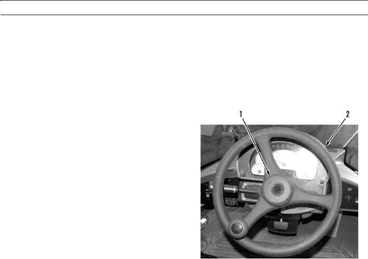
Connect wire (3) to horn button (1).
5.
Press horn button (1) into center of steering wheel (2).
427-B0200
WAR N I N G
Before operating equipment, secure the steering frame lock in the stowed position. DO NOT operate
machine with steering frame lock connected. Failure to lock steering frame lock into the stowed position
before operating can result in loss of steering and injury or death to personnel.
6.
Secure steering frame lock in stowed position (TM 5-3805-290-10).
7.
Drive machine to verify correct operation of steering system (TM 5-3805-290-10).
END OF WORK PACKAGE
0098 00-3/(0098 00-4 Blank)