TM 5-3805-290-23-2
RIDE CONTROL VALVE MAINTENANCE - CONTINUED
0123 00
COMPONENT TRANSFER
1.
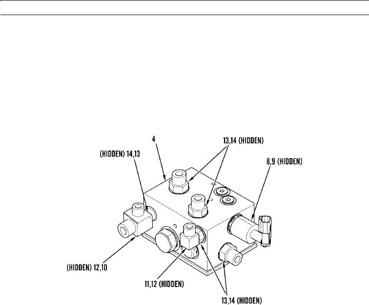
Remove solenoid (8) and O-ring (9) from ride control valve (4). Discard O-ring.
2.
Remove T (10), elbow (11), and two O-rings (12) from ride control valve (4). Discard O-rings.
3.
Remove five connectors (13) and O-rings (14) from ride control valve (4). Discard O-rings.
N OT E
Apply a thin coat of clean oil to all O-rings before installation.
4.
Install five new O-rings (14) and connectors (13) on ride control valve (4).
5.
Install two new O-rings (12), T (10), and elbow (11) on ride control valve (4).
6.
Install new O-ring (9) and solenoid (8) on ride control valve (4).
427-B0214
INSTALLATION
1.
Install ride control valve (4), two washers (7), and bolts (6) on machine.
2.
Connect wiring harness (5).
3.
Install six new O-rings (3) and connect five hose assemblies (1) and hose assembly (2) to ride control valve (4).
WAR N I N G
Before operating equipment, secure the steering frame lock in the stowed position. DO NOT operate
machine with steering frame lock connected. Failure to lock steering frame lock into the stowed position
before operating can result in loss of steering and injury or death to personnel.
4.
Secure steering frame lock in stowed position (TM 5-3805-290-10).
5.
Operate machine using ride control (TM 5-3805-290-10).
6.
Shut down engine (TM 5-3805-290-10).
7.
Check for hydraulic oil leaks.
END OF WORK PACKAGE
0123 00-3/(0123 00-4 Blank)

