
TM 5-3805-290-23-2
PILOT OPERATED CONTROL (JOY STICK) AND HYDRAULIC
LOCKOUT VALVE REPLACEMENT - CONTINUED
0188 00
REMOVAL - CONTINUED
14.
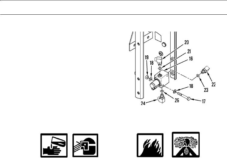
Disconnect hoses from shutoff valve (16).
15.
Remove two bolts (17), four washers (18), two nuts
(19), and shutoff valve (16) from machine.
16.
Remove elbow (20) and O-ring (21) from shutoff
valve (16). Discard O-ring.
17.
Remove elbow (22) and O-ring (23) from shutoff
valve (16). Discard O-ring.
18.
Remove elbow (24) and O-ring (25) from shutoff
valve (16). Discard O-ring.
427-B1788
CLEANING AND INSPECTION
WARN I N G
Solvent cleaning compound MIL-PRF-680 Type III is an environmentally compliant and low-toxic
material. However, it may be irritating to the eyes and skin. Use protective gloves and goggles. Use in
well-ventilated areas. Keep away from open flames and other sources of ignition. Failure to do so may
result in injury or death to personnel.
Particles blown by compressed air are hazardous. DO NOT exceed 15 psi (103 kPa) nozzle pressure
when drying parts with compressed air. DO NOT direct compressed air against human skin. Make sure
air stream is directed away from user and other personnel in the area. To prevent injury, user must
wear protective goggles or face shield. Failure to follow this warning may result in injury to personnel.
1.
Clean all parts and surfaces with solvent cleaning compound.
2.
Dry parts with compressed air.
3.
Inspect all parts for wear, pitting, cracks, or corrosion and replace if necessary.
4.
Inspect oil passages to ensure they are clean and unobstructed.
INSTALLATION
N OT E
Apply a thin coat of clean oil to all O-rings prior to installation.
1.
Install new O-ring (25) and elbow (24) on shutoff valve (16).
2.
Install new O-ring (23) and elbow (22) on shutoff valve (16).
3.
Install new O-ring (21) and elbow (20) on shutoff valve (16).
4.
Install shutoff valve (16), two nuts (19), four washers (18), and two bolts (17) on machine.
5.
Connect hoses to shutoff valve (16).
0188 00-5