
TM 5-3805-290-23-2
PILOT OPERATED CONTROL (JOY STICK) AND HYDRAULIC
LOCKOUT VALVE REPLACEMENT - CONTINUED
0188 00
INSTALLATION - CONTINUED
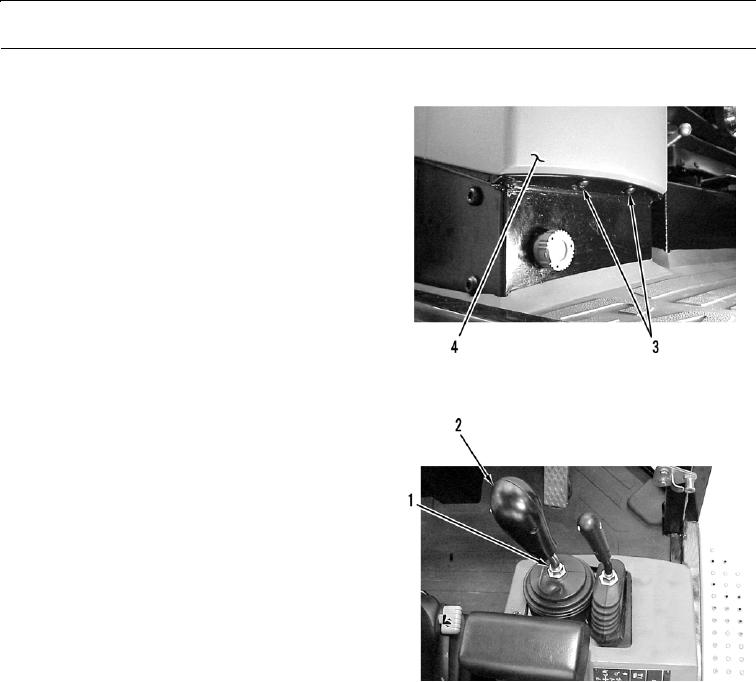
14.
Install two torx screws (3) in bottom of cover (4).
Tighten screws to 4.4 0.7 lb-ft (6 1 Nm).
427-B0770
15.
Install handle (2) in proper position and tighten nut
(1).
427-B0768
WAR N I N G
Before operating equipment, secure the steering frame lock in the stowed position. DO NOT operate
machine with steering frame lock connected. Failure to lock steering frame lock into the stowed posi-
tion before operating can result in loss of steering and injury or death to personnel.
16.
Secure steering frame lock in stowed position (TM 5-3805-290-10).
17.
Check hydraulic fluid level (TM 5-3805-290-10).
18.
Run engine until normal operating temperature is reached (TM 5-3805-290-10).
19.
Shut down engine (TM 5-3805-290-10).
20.
Check for hydraulic leaks.
END OF WORK PACKAGE
0188 00-8