
TM 5-3805-290-23-2
AIR CONDITIONING SYSTEM SERVICE - CONTINUED
0191 00
EVACUATION
0191 00
1.
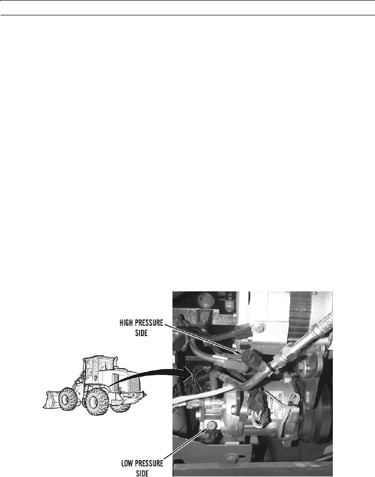
After refrigerant is recovered from system, ensure that low pressure valve (11) and high pressure valve (12) are closed.
2.
Disconnect charging hose (7) of manifold gage set (1) from recovery station inlet.
3.
Check oil level in vacuum pump (18).
4.
Plug vacuum pump (18) into electrical outlet.
5.
Connect charging hose (7) to inlet fitting on vacuum pump (18).
6.
Open low pressure valve (11) and high pressure valve (12) on manifold gage set (1).
7.
Turn on vacuum pump (18).
N OT E
Vented exhaust valve must remain closed until vacuum pump has started.
8.
Open vented exhaust valve (19).
N OT E
Between 28 in. Hg to 29 in. Hg (95 to 98 kPa) is the required pressure specification at sea level. For
every 1,000 ft (305 m) above sea level, decrease required specification by 1 in. Hg (3 kPa).
9.
Operate vacuum pump (18) until low pressure gage (20) indicates pressure between 28 in. Hg to 29 in. Hg (95 to
98 kPa), then close vented exhaust valve (19). Operate vacuum pump for minimum of 90 minutes after closing vented
exhaust valve.
N OT E
Maximum vacuum loss in 5 minutes must not exceed 2 in. Hg (7 kPa). Excessive vacuum loss may
indicate a system leak.
10.
Close low pressure valve (11) and high pressure valve (12).
11.
Turn off vacuum pump (18).
427-B2003
0191 00-4