
TM 5-3805-291-23-1
THEORY OF OPERATION - CONTINUED
0003 00
ENGINE
0003 00
1.
General. Engine consists of five major components:
cylinder block, pistons, rings, and connecting rods,
crankshaft, camshaft, and vibration damper. Engine
lubrication, cooling, and air inlet/exhaust are covered
in separate subsections.
2.
Cylinder Block.
a.
Cylinder block is a unique design with a deep
counterbore that supports a cylinder liner. Cylin-
der block also forms a coolant jacket. Two oil
manifolds are provided in cylinder block for
engine lubrication. Manifold on lower right side
of cylinder block provides oil to these compo-
nents:
Piston cooling jets
427-C1709
Crankshaft bearings
Oil filter base
b.
Manifold on upper left side of cylinder block provides oil to these components:
Camshaft bearings
Valve mechanism
c.
Right side manifold supplies oil to left side man-
ifold. Oil travels through a cut above No. 1 main
bearing and a cut above No. 4 main bearing.
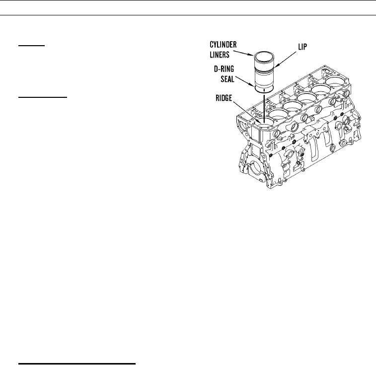
d.
Cylinder liners are seated on a ridge in middle of cylinder wall between crankcase and coolant jacket. Ridge is cre-
ated by a counterbore in cylinder block. Cylinder liners have a lip which rests on ridge. Coolant jacket seals are
located in upper and middle regions of cylinder liners. Lower barrier uses a D-ring seal located above cylinder
liner seating surface. Upper barrier is head gasket which is above coolant jacket.
e.
Cylinder block has seven main bearings to support crankshaft. Each main bearing cap is fastened to cylinder block
with two bolts.
3.
Pistons, Rings, and Connecting Rods.
a.
Engine's high compression ratio requires use of steel one-piece pistons. Each piston has three rings:
Compression ring
Intermediate ring
Oil ring
b.
Rings are located in piston grooves. Rings seal crankcase from combustion gases and provide control of engine oil.
Compression ring design is a barrel face with a plasma face coating. Intermediate ring design is a tapered shape
with a chrome finish. Oil ring is double-railed with a coil spring expander. Oil ring has a ground profile and a
chrome finish.
c.
Connecting rod is a conventional design. Cap is fastened to shank by two bolts threaded into shank. Each side of
connecting rod small end is machined at an angle of 12 degrees to fit within piston cavity. This design allows a
larger surface area on each piston and connecting rod, which minimizes bearing load.