
TM 5-3805-291-23-1
THEORY OF OPERATION - CONTINUED
0003 00
ENGINE - CONTINUED
b.
Coolant Flow.
(1)
Water pump pulls coolant from bottom of radiator. Water pump is located on right hand side of front tim-
ing gear housing.
(2)
Water pump impeller rotates at 1.17 times engine speed. Water pump is driven by an idler gear which is
turned by crankshaft gear. Water pump shaft is supported by two ball bearings. One ball bearing is located
in water pump housing and one is located in front timing gear housing. Water pump impeller face is open.
Impeller is made of cast iron with a rear cover that is an aluminum die casting. Water pump seal is a car-
tridge seal located on inlet side of water pump. Seal provides good water flow around itself for cooling.
(3)
Coolant is pumped through engine oil cooler, then flows to supply manifold located in cylinder block,
which distributes coolant around upper portion of cylinder liners. At each cylinder, coolant flows from cyl-
inder liner to cylinder head. Cylinder head is divided into single-cylinder cooling sections. In cylinder
head, coolant flows across center of cylinder and across injector seat boss. At center of cylinder, coolant
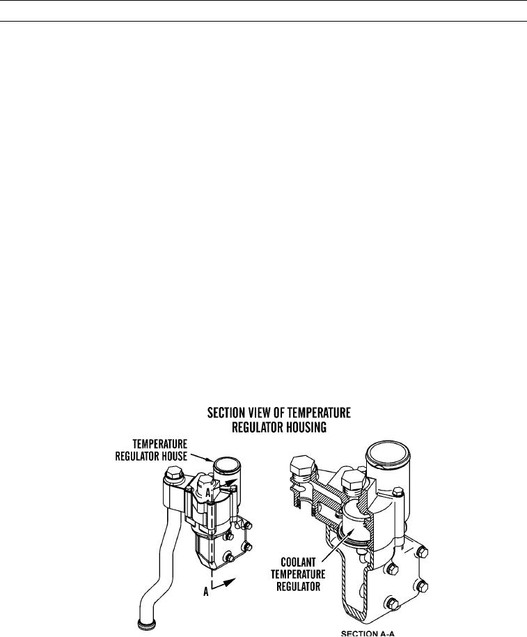
flows around injector sleeve over exhaust port. Coolant then exits into return manifold. Return manifold
collects coolant from each cylinder and directs flow to temperature regulator housing. When coolant tem-
perature regulator is closed, coolant flows through bypass tube, allowing coolant to flow directly back to
water pump for recirculation by bypassing radiator. When coolant temperature regulator is open, coolant
flows through radiator and back to water pump inlet.
c.
Supply Manifold. Cooling is only provided for upper portion of cylinder liner above seal in cylinder block. Cool-
ant enters cylinder block at each cylinder through slits in supply manifold. Supply manifold is an integral casting in
cylinder block. Coolant flows around cylinder liner circumference and into cylinder head through a single drilled
passage for each liner. Coolant flow is split at each cylinder liner to 60 percent flows around cylinder liner and
remainder flows directly to cylinder head.
427-C1716
0003 00-8