TM 5-3805-291-23-1
THEORY OF OPERATION - CONTINUED
0003 00
ENGINE - CONTINUED
(1)
Alternator. Alternator is driven by a belt from crankshaft pulley. This alternator is a three-phase, self-rec-
tifying charging unit, and regulator is part of alternator. Alternator design has no need for slip rings and
rotor assembly is the only moving part. All conductors that carry current are stationary. These conductors
are in circuit:
Field winding
Stator windings
Six rectifying diodes
Regulator circuit components
(2)
Rotor Assembly. Rotor assembly has many magnetic poles that resemble fingers with air space between
each opposite pole. Poles have residual magnetism which produces a small magnetic field between poles.
As rotor assembly begins to turn between field winding and stator windings, a small amount of alternating
current (ac) is produced in stator windings from small magnetic field. Ac current is changed to direct cur-
rent (DC) when it passes through rectifier bridge diodes. DC current is used for charging battery, supply
low amperage accessory circuit, and strengthening magnetic field.
(3)
Voltage Regulator. Voltage regulator is a solid-state electronic switch which senses system voltage. Volt-
age regulator switches ON and OFF many times per second to control alternator field current. Alternator
uses field current to generate required voltage output.
f.
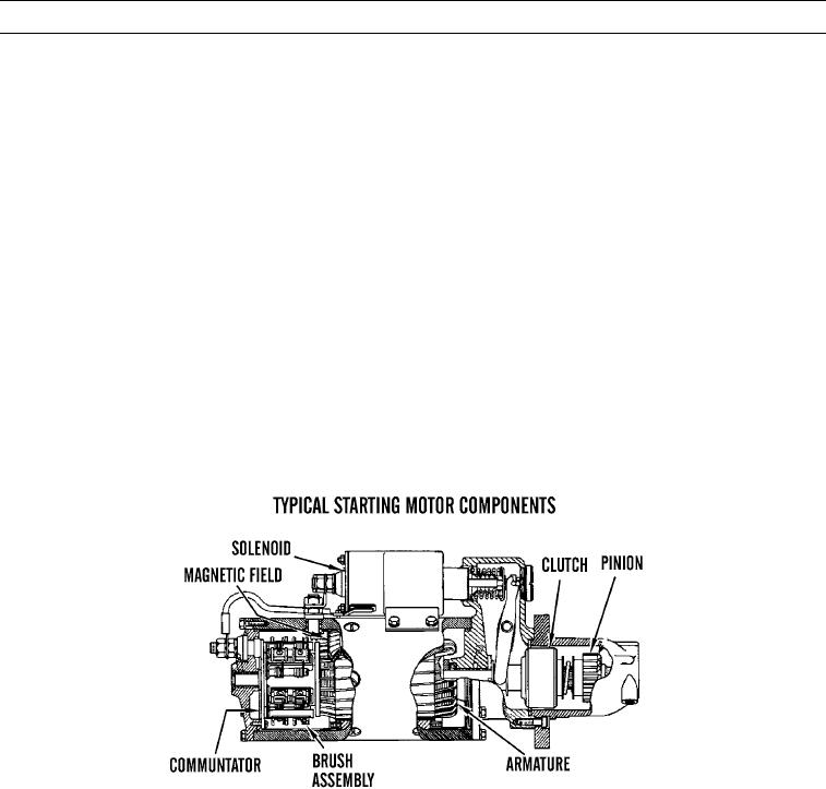
Starting System Components.
427-C1723
0003 00-18

