
TM 5-3805-291-23-1
THEORY OF OPERATION - CONTINUED
0003 00
POWERTRAIN
0003 00
427-C1724
1.
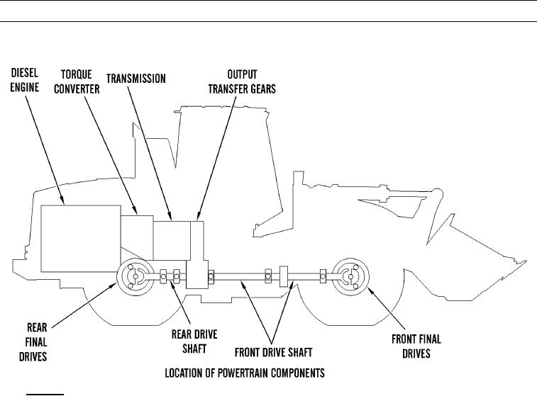
General.
a.
Power from diesel engine is sent from flywheel to torque converter. Torque converter is splined to transmission
and fastened to engine flywheel with bolts. Power flows directly from torque converter to transmission front pump.
b.
Transmission output shaft is connected to input gear in output transfer gear case by splines. Power is sent through
input gear to output gear. Output gear sends power through rear drive shaft to rear differential and to front differen-
tial through front drive shafts. Bevel gear and pinion of each differential sends power to final drives through differ-
entials and sun gear shafts. Axle shafts transfer power from final drives and to wheels.
0003 00-20