
TM 5-3805-291-23-1
THEORY OF OPERATION - CONTINUED
0003 00
POWERTRAIN - CONTINUED
21.
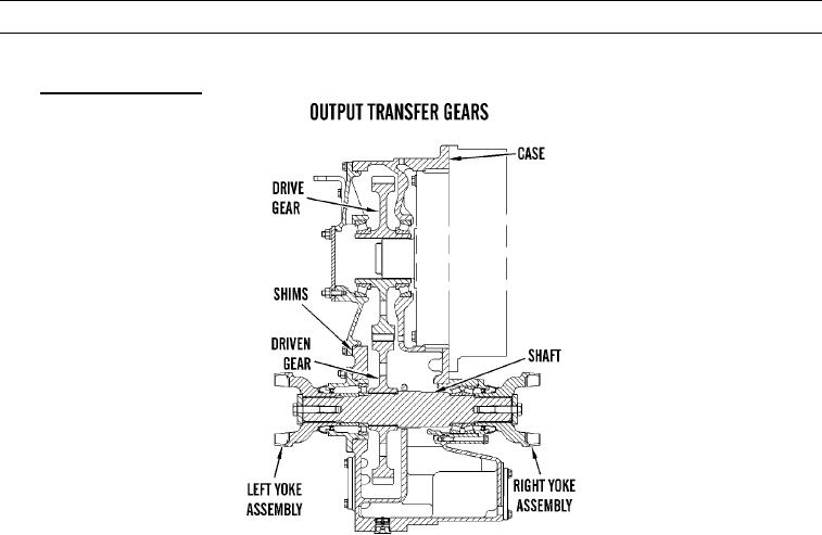
Output Transfer Gears.
427-C1739
a.
General.
(1)
Output transfer gears are at output side of transmission. Transmission output shaft is connected to drive
gear by splines.
(2)
Drive gear is engaged with driven gear, which is connected to shaft by splines. Yoke assemblies are con-
nected to shaft by splines. Left yoke assembly is connected to short drive shaft that is connected to rear dif-
ferential. Right yoke assembly is connected to drive shaft, which is connected to pillow block bearing and
front differential.
(3)
Power flow in output transfer gears goes from transmission output shaft to drive gear, to driven gear, to
shaft. At shaft, power flow divides. Some power goes from left yoke assembly through a drive shaft to rear
differential. Some power goes from right yoke assembly through a drive shaft, through bearing cage, to
front differential.
(4)
Shims are used to adjust end play of gear.
0003 00-55