TM 5-3805-291-23-1
THEORY OF OPERATION - CONTINUED
0003 00
BRAKE AND HYDRAULIC FAN SYSTEM - CONTINUED
(4)
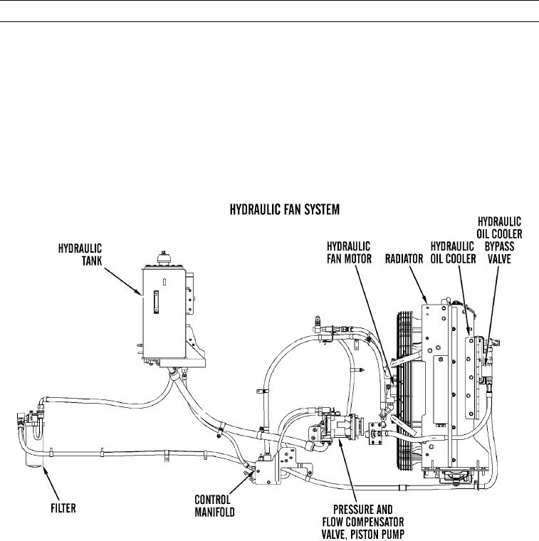
When oil temperature increases and oil pressure decreases, spring force in hydraulic oil cooler bypass
valve is greater than force of oil pressure acting on spring. This allows bypass valve to close. Hydraulic oil
flows through hydraulic oil cooler and hydraulic oil filter, through axle oil cooler, and into hydraulic tank.
(5)
Hydraulic fan system controls fan speed, allowing fan speed to decrease in cool ambient temperature or a
light work application. Fan speed is controlled by four temperature sensors which send data to engine
ECM. Engine ECM interprets data from all four sensors and sends any change in current to control mani-
fold. A change in current to valve will change oil flow from control manifold to spools in pressure and
flow compensator valve. Spool movement in pressure and flow compensator valve will decrease swash-
plate angle in hydraulic fan pump. By changing swashplate angle, oil volume from hydraulic pump will
decrease and swashplate angle will slow oil flow to hydraulic fan motor.
427-C1778
(6)
Pressure and flow compensator valve, which controls pump flow, is mounted on top of hydraulic fan
pump. Valve contains a flow control spool and a pressure cutoff spool. Settings on both spools can be
adjusted.
0003 00-104

