
TM 5-3805-291-23-1
THEORY OF OPERATION - CONTINUED
0003 00
STEERING SYSTEM - CONTINUED
(1)
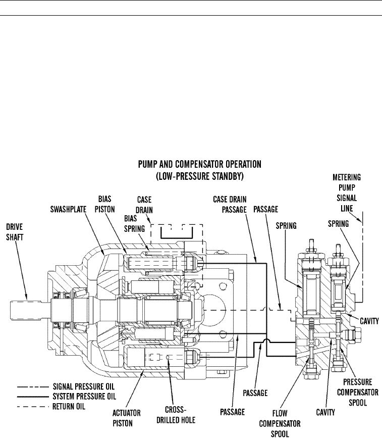
Decreased flow demand causes a signal pressure in metering pump signal line. Signal pressure in line
combines with force of spring in pressure compensator cavity. This combined force is less than pump pres-
sure in passage, causing pressure compensator spool to move upward.
(2)
Oil behind actuator piston cannot flow through passage to case drain. Pump oil now flows through passage
to pressure compensator spool, then past spool, through passage, and to actuator piston.
(3)
Pump pressure behind actuator piston is now greater than combined force of bias piston and bias spring.
Swashplate angle decreases, decreasing pump output and system pressure.
(4)
When lower flow requirements are met, flow compensator spool moves down to metering position.
Swashplate maintains an angle sufficient to provide lower required pressure. If operator does not turn
steering wheel, pump will return to low-pressure standby.
l.
Low-Pressure Standby.
427-C1789
0003 00-113