TM 5-3805-291-23-1
THEORY OF OPERATION - CONTINUED
0003 00
ELECTRO-HYDRAULIC SYSTEM - CONTINUED
c.
Implement piston pump and steering piston pump are located under cab, mounted in-line to torque converter hous-
ing.
d.
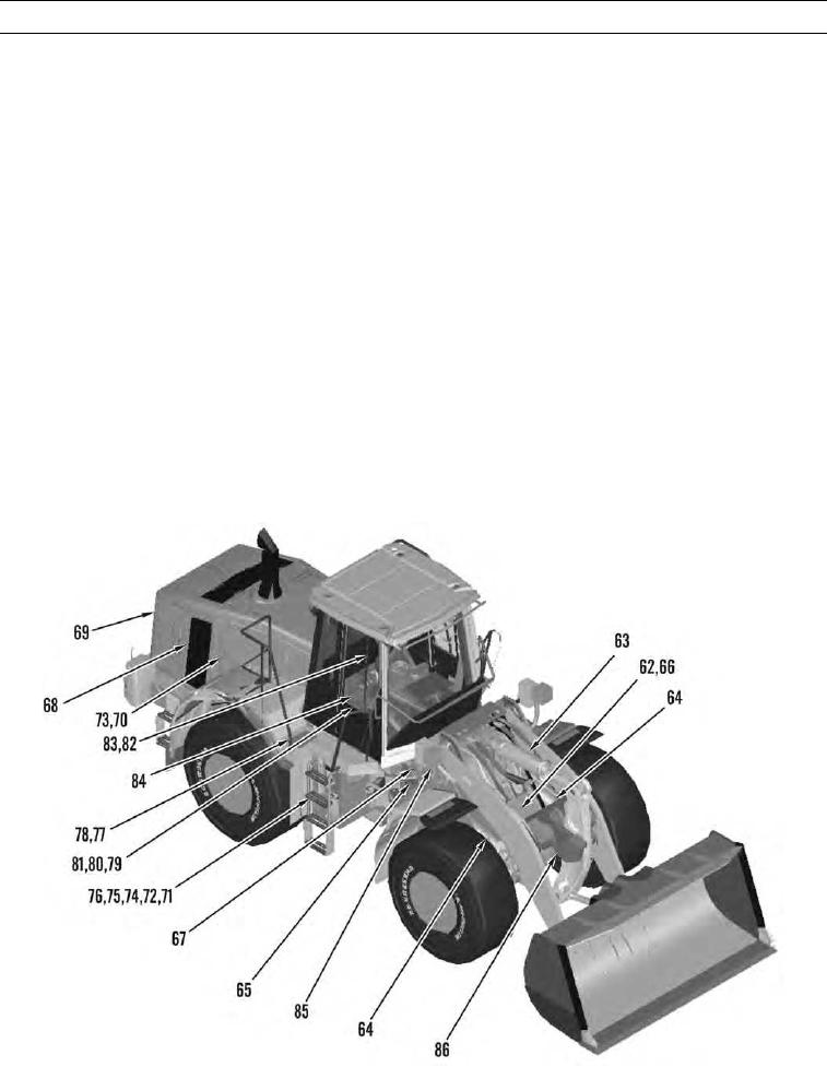
Hydraulic tank (75) is located on right side of machine. Breaker relief valve (74) is mounted on hydraulic tank.
When an operator depresses breaker relief valve, pressure inside hydraulic tank is released.
e.
Ride control system provides a means for dampening bucket forces which produce a pitching motion as machine
travels over rough terrain.
f.
Dead engine lower manual valve (67) is located in front of articulation joint. Manual valve is used to lower lift
arms when there is an electrical failure.
g.
Implement ECM (77) is located on right side and to rear of cab.
h.
Implement piston pump provides pump supply oil to main control valve (62). A remote pressure tap for measuring
implement pressure is located at articulation joint on right side.
i.
Implement piston pump also supplies pilot oil pressure to pilot system. A pressure tap for measuring pilot pressure
is located by main control valve near pilot oil accumulator.
j.
Main control valve (62) is mounted on front end of frame.
k.
Main load sensing relief valve is mounted on main control valve (62). Line relief valves are also attached to main
control valve. Main control valve controls pump supply oil to implement cylinders.
l.
Joystick control is equipped with three-position sensors. Third function sensor is controlled by a thumb wheel built
into joystick handle. Position sensors send joystick handle position to implement ECM. Joystick control is not
equipped with electromagnets for detents. Joystick control is equipped with soft detents (refer to Sensors) in this
work package.
427-C1808
0003 00-138

