TM 5-3805-291-23-1
THEORY OF OPERATION - CONTINUED
0003 00
ELECTRO-HYDRAULIC SYSTEM - CONTINUED
427-C1810
n.
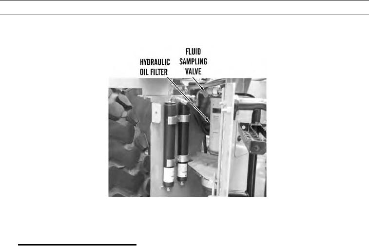
Hydraulic oil filter is located on right side of machine behind service door. Sampling valve is located on hydraulic
oil filter. Hydraulic oil filter is in return line from hydraulic fan system. Fluid sampling valve is located above
hydraulic oil filter, and is available to check hydraulic oil quality.
2.
Implement Electronic Control System.
a.
Implement ECM monitors position of joystick position sensors located in operator compartment. When joystick is
moved, implement ECM detects amount of position sensor movement, then activates corresponding solenoid
valve. Implement ECM activates solenoid valve in proper amount to move work tool at appropriate speed.
b.
Implement ECM electronically controls pilot proportioning solenoid valves, then solenoid valves control move-
ment of stems in main control valve for work tool and any auxiliary hydraulic attachments. Position sensors detect
movement in joystick and sensors will develop a signal. Implement ECM reads signals and activates appropriate
pilot proportioning solenoid valve. As a position sensor begins to rotate, implement ECM sends a small amount of
current to solenoid valve to move cylinder. As rotation of position sensor begins to increase, implement ECM
increases amount of current to solenoid valve. Speed of cylinder increases proportionally in response.
c.
Hydraulic lockout solenoid valve is activated by implement ECM whenever engine is running. Hydraulic lockout
solenoid valve is an ON/OFF valve that controls pilot oil flow through oil manifold pilot valve. If hydraulic lock-
out switch is in LOCKED position, implement ECM will not supply current to hydraulic lockout solenoid valve.
0003 00-140

