
TM 5-3805-291-23-1
THEORY OF OPERATION - CONTINUED
0003 00
AIR CONDITIONING SYSTEM - CONTINUED
Refrigerant Accumulator
0003 00
427-C2000
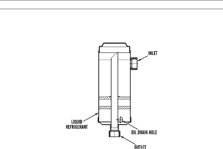
1.
The accumulator is located at the outlet of the evaporator coil. The accumulator separates the liquid refrigerant from the
refrigerant vapor that passes through the evaporator coil. The accumulator retains the liquid refrigerant that is separated.
Also, the accumulator releases the vapor to the compressor.
2.
The oil drain hole is located in the bottom of the accumulator. The oil drain hole will drain refrigerant oil that is sepa-
rated. The oil drain hole will also drain some of the liquid refrigerant. This liquid refrigerant will go back to the com-
pressor.
3.
The flow of refrigerant out of the accumulator to the compressor is mostly vapor. The vapor contains a small amount of
liquid refrigerant. This liquid refrigerant comes from the oil drain hole.
0003 00-184