
TM 5-3805-291-23-1
THEORY OF OPERATION - CONTINUED
0003 00
AIR CONDITIONING SYSTEM - CONTINUED
Refrigerant Compressor
0003 00
427-C2001
1.
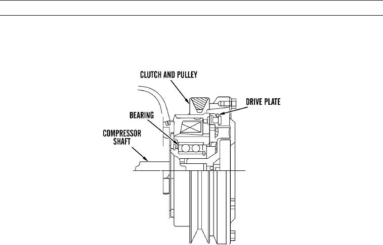
The compressor is driven by the engine. A belt connects the engine to the clutch and pulley assembly. The pulley is
located on the clutch. The drive plate is fastened to the shaft of the compressor. The clutch and pulley assembly turns on
the bearing. The clutch and pulley assembly are not connected to the shaft. The electric current from the thermostat con-
trols a magnetic field in the coil assembly.
2.
The magnetic field pulls the drive plate against the clutch and pulley assembly. The clutch and the pulley assembly turns
the shaft that operates the compressor. When the current to the coil assembly is stopped, the magnetic field is removed.
This allows the drive plate to move away from the clutch and pulley assembly. The clutch and the pulley assembly will
turn freely on the bearing. The sequence of connecting and disconnecting the pulley to the compressor shaft is called
compressor cycling. The compressor cycling is controlled by the thermostat. The thermostat is controlled by the capil-
lary tube, which is installed between the fins of the evaporator coil.
0003 00-185