
TM 5-3805-291-23-1
HOW TO USE MSD WITH ET - CONTINUED
0005 00
STATUS GROUPS - CONTINUED
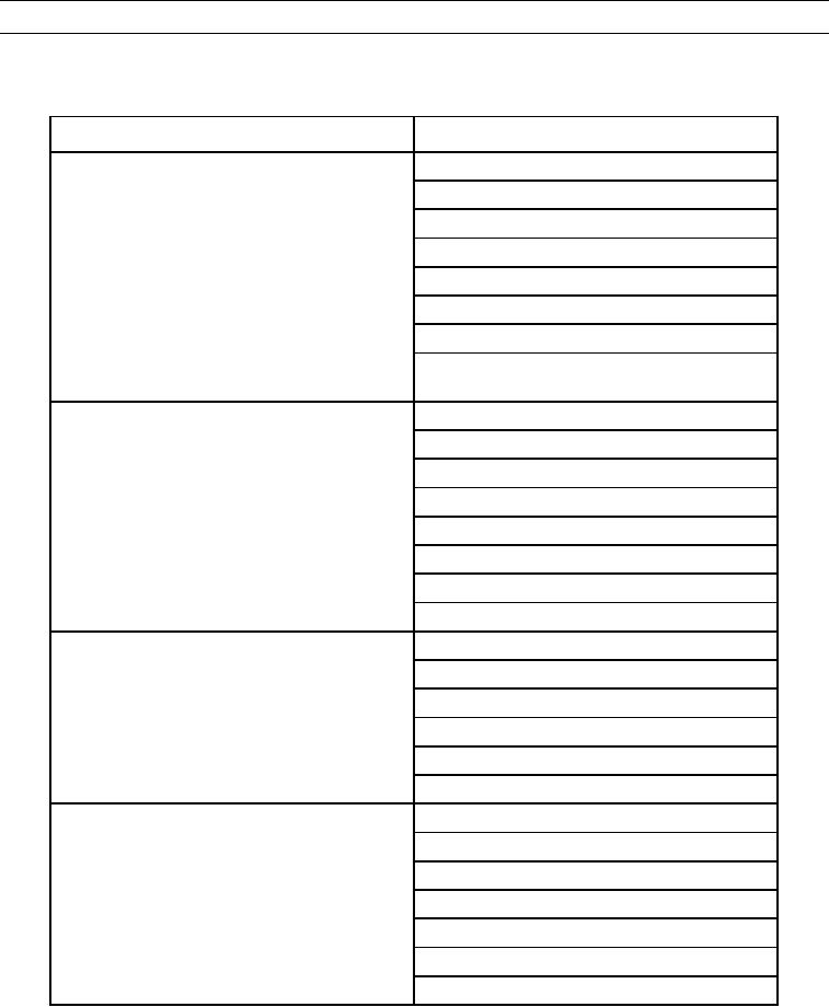
Table 4. Implement ECM - Continued.
Status Screen
Parameters
Screen 8 (System Input)
System Voltage
Fuel Gauge
Implement Pilot Supply Solenoid
Implement Lockout Switch Position
Hydraulic Oil Temperature
Hydraulic Filter Bypass Status
Security System Immobilizer Status
Hydraulic System Warning Indicator **From:
Graphical Display Module
Screen 9 (Payload Control Loading Status)
Bucket Payload Data
Bucket Payload
Weigh Cycle Total Truck Payload
Target Payload
Remaining Payload To Load
Load Cycle Pass Count
Load Cycle Start Time
Load Cycle End Time
Screen 10 (Payload Control System Status)
Lift Cylinder Head Pressure
Lift Cylinder Rod End Pressure
Lift Cylinder Position
Payload Store Switch
Payload Re-weigh Switch Position
Payload Zero Switch Position
Screen 11 (Payload Control Setting Status)
Automatic Operator ID Feature
Automatic Truck ID Feature
Automatic Material ID Feature
Warmup Lifts Feature
Zero Reminder Feature
Tilt Sensor
Payload Memory Remaining
END OF WORK PACKAGE
0005 00-15/(0005 00-16 Blank)