
TM 5-3805-291-23-1
ELECTRICAL SYSTEM TESTS, INSPECTIONS, AND ADJUSTMENTS - CONTINUED
0013 00
5V ENGINE PRESSURE SENSOR SUPPLY CIRCUIT TEST - CONTINUED
427-C0636
427-C0635
427-C0635
h.
Perform 10 lb (45 N) pull test on each wire in ECM connector associated with +5V sensor supply.
i.
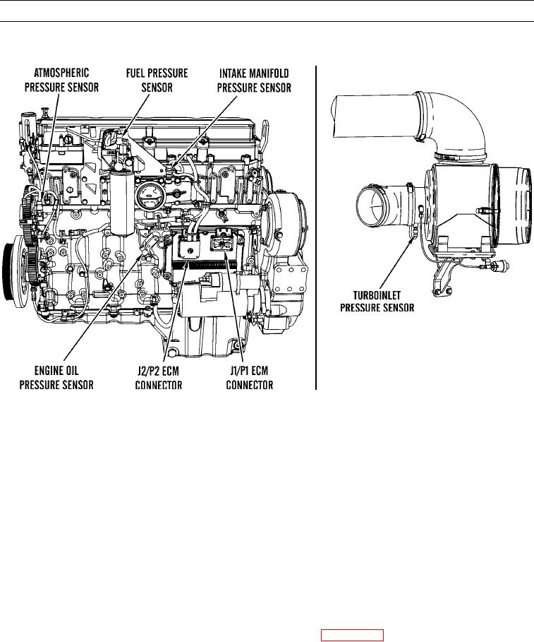
Check J2/P2 ECM connector (socket-head screw) for proper torque of 60 lb-in. (7 Nm).
j.
Check J1/P1 ECM connector (socket-head screw) for proper torque of 55 lb-in. (6 Nm).
k.
Check harness and wiring for abrasion and pinch points from sensors back to ECM.
Expected Results. All connectors, pins, and sockets should be completely coupled and/or inserted and harness and
l.
wiring should be free of corrosion, abrasion, or pinch points.
(1)
If results are OK, proceed to step 2.
(2)
If results are not OK, replace wiring harness in question (WP 0195 00 thru WP 0201 00). Ensure seals are
properly in place and connectors are securely connected. Verify repair eliminates problem.
2.
Check for active diagnostic codes.
a.
Connect MSD equipped with ET software to data link connector (WP 0005 00).
b.
Turn engine start switch to ON position while engine is OFF (TM 5-3805-291-10).
c.
Retrieve active and logged diagnostic codes on MSD. Check and record any diagnostic codes.
0013 00-8