TM 5-3805-291-23-1
ELECTRICAL SYSTEM TESTS, INSPECTIONS, AND ADJUSTMENTS - CONTINUED
0013 00
INJECTOR SOLENOID CIRCUIT TEST - CONTINUED
427-C0698
e.
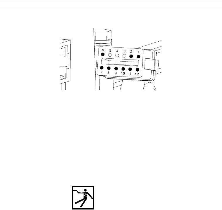
Insert one end of jumper wire into P300 connector socket for suspect injector's supply wire. Insert other end of
jumper wire into P300 connector socket for suspect injector's return wire. This will replace injector solenoid with
a short circuit.
f.
Perform injector solenoid test at least two times.
g.
Repeat this test two times for each suspect circuit. Stop injector solenoid test before handling jumper wire. Restore
wiring to original configuration.
h.
ET displays "Short" for each jumpered circuit.
Expected Results. Harness between ECM and P300 connector does not have an open circuit.
i.
(1)
If results are OK, ET displays "Short" for each circuit that was jumpered. Proceed to step 7.
(2)
If results are not OK, ET displays "Open" for cylinder with jumper wire. There is a problem in wiring
between ECM and P300 connector. Proceed to step 8.
7.
Check harness between ECM and valve cover base for a short circuit.
WARN I N G
Electronic fuel injector system uses 90 to 120V. Do not touch any components during testing. Failure to
comply may result in injury to personnel or damage to equipment.
a.
Place battery disconnect switch in OFF position (TM 5-3805-291-10).
b.
Disconnect P300 connector.
c.
Place battery disconnect switch in ON position (TM 5-3805-291-10).
d.
Perform injector solenoid test at least two times.
Expected Results. All cylinders indicate "Open" on ET.
e.
(1)
If results are OK, all cylinders indicate "Open" on ET. Proceed to step 8.
(2)
If results are not OK, one or more cylinders indicate "Short" on ET. Record cylinders that indicate "Short".
Proceed to step 9.
0013 00-59

