
TM 5-3805-291-23-1
HYDRAULIC SYSTEM TESTS, INSPECTIONS, AND ADJUSTMENTS - CONTINUED
0017 00
MAIN CONTROL VALVE (MSD) CALIBRATION
0017 00
N OT E
Calibrations are automatic.
If equipped with linkage position sensors, calib ations for lift and tilt valves will be automatic.
r
Auxiliary control is a manual calibration. However, the auxiliary control calibration is still
described in section for automatic calibration since this is normal state for calibration of auxiliary
control. Manual calibration starts same way as automatic calibration. MSD will automatically
display appropriate calibrations.
Ensure there are no active diagnotic codes for hardware faults.
s
Joystick sensors are factory calibrated and shoud not require calibration. However, calibration
l
may be necessary if problems exist activating detents.
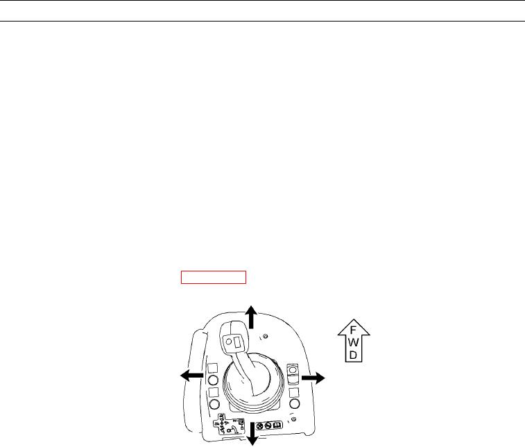
Up arrow refers to LOWER position. Down arro refers to RAISE position. Right arrow refers
w
to DUMP position. Left arrow refers to TILT BACK position.
For auxiliary control, up arrow refers to au iliary lever in FORWARD position. Down arrow
x
refers to auxiliary lever in REARWARD position.
For additional information on joystick control, refer to TM 5-3805-291-10.
1.
Connect MSD to diagnostic connector (WP 0005 00).
427-C0783
2.
Start and run engine at low idle (TM 5-3805-291-10).