
TM 5-3805-291-23-2
INTAKE/EXHAUST VALVE LASH ADJUSTMENT - CONTINUED
0179 00
INTAKE VALVE ADJUSTMENT - CONTINUED
N OT E
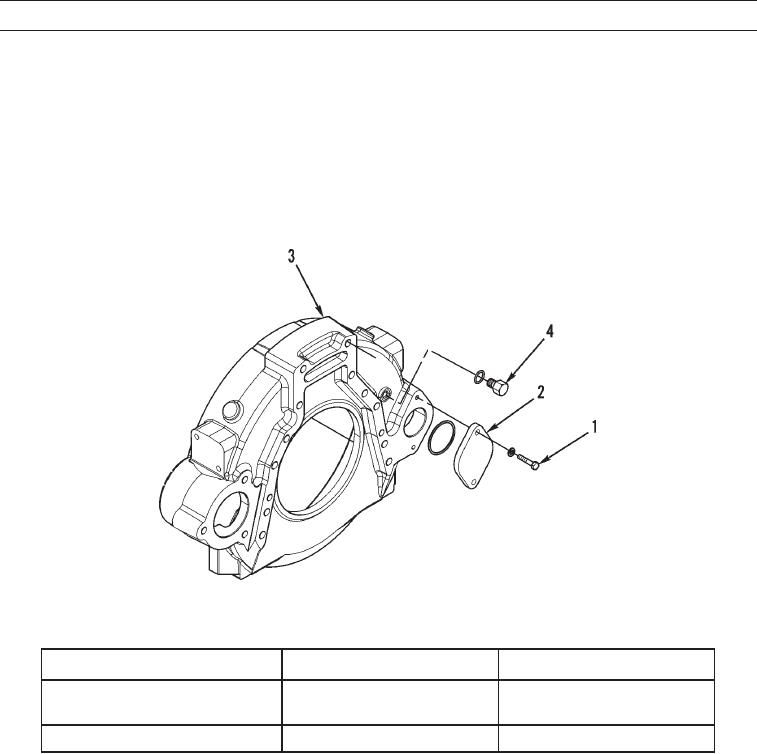
Direction of engine rotation is counterclockwise, as the engine is viewed from the flywheel end.Turn
flywheel in direction of engine rotation.
If flywheel is turned beyond point of engagement with timing pin, flywheel must be turned clockwise
approximately 30 degrees. Then turn flywheel counterclockwise until timing pin engages hole in fly-
wheel. This procedure removes play from gears when No. 1 piston is at top-center position.
d. Turn flywheel until timing pin engages with hole in flywheel.
427-C0600
Table 1. Intake Valve Lash Adjustment.
Inlet Valves
Exhaust Valves
TC Compression Stroke (1)
0.0150 0.0031 in.
0.0252 0.0031 in.
Valve Lash
(0.38 0.08 mm)
(0.64 0.08 mm)
1-2-4
1-3-5
Cylinders
(1)
Position for No. 1 cylinder
0179 00-3