TM 5-3805-291-23-2
INTAKE/EXHAUST VALVE LASH ADJUSTMENT - CONTINUED
0179 00
EXHAUST VALVE ADJUSTMENT
1.
Put No. 6 piston at top center position on compression stroke.
Table 2. Exhaust Valve Lash Adjustment.
Inlet Valves
Exhaust Valves
TC Compression Stroke (1)
0.0150 0.0031 in.
0.0252 0.0031 in.
Valve Lash
(0.38 0.08 mm)
(0.64 0.08 mm)
3-5-6
2-4-6
Cylinders
(1)
Position for No. 6 cylinder 360 from TC Compression Stroke
2.
Adjust valve lash according to Table 2.
a.
Lightly tap rocker arm (5) at top of adjustment screw (6). This will ensure lifter roller seats.
b.
Loosen adjustment locknut (7).
c.
Place appropriate feeler gage between rocker arm (5) and valve bridge (8).
d.
Turn adjustment screw (6) in clockwise direction. Slide feeler gage between rocker arm (5) and valve bridge (8).
Continue turning adjustment screw until a slight drag is felt on feeler gage.
e.
Tighten adjustment locknut (7) to 22 5 lb-ft (30 7 Nm).
N OT E
DO NOT allow adjustment screw to turn while you are tightening adjustment locknut.
f.
Recheck valve lash after tightening adjustment locknut (7).
3.
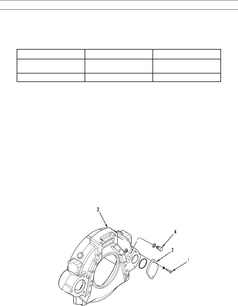
Remove timing pin with timing pin adapter from timing hole.
4.
Install plug (4) in timing hole.
5.
Install cover (2) and two bolts (1) on flywheel housing (3).
427-C0600
0179 00-5

