
TM 5-3805-291-23-2
SEPARATE FRONT LOADER FRAME AND REAR FRAME - CONTINUED
0211 00
CONNECTION - CONTINUED
N OT E
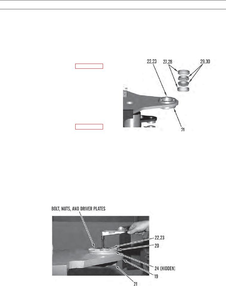
The following steps are for assembling upper hitch bearings.
18.
Position cap (21) and install three washers (23) and bolts (22) equally spaced on cap. Ensure cap is seated firmly against
frame of machine. Apply grease to bores.
19.
Lower temperature of new lower bearing cup (28) and
use Bushing driver set (Item 20, WP 0232 00) to
install so lower bearing cup makes contact with cap
(21).
20.
Apply clean oil to new lower bearing (30) and install
in lower bearing cup (28).
21.
Apply clean oil to new upper bearing (29) and install
next to lower bearing (28).
22.
Lower temperature of new upper bearing cup (27) and
use Bushing driver set (Item 20, WP 0232 00) to
install so upper bearing cup makes contact with upper
427-C1053
bearing (29).
23.
Remove three bolts (22) and washers (23) from cap (21).
24.
Remove cap (21) from machine.
25.
Position shims (24) on upper hitch (19).
26.
Position caps (20 and 21) and install three washers (23) and bolts (22) evenly spaced on cap (21).
27.
Install 1/4 NC x 3 3/4-in. bolt, two 1/4 NC nuts, and two driver plates. Use torque wrench to measure rolling torque.
Adjust number of shims (24) to achieve rolling torque of 124 to 18 lb-in. (14 to 2 Nm).
28.
Remove three bolts (22), washers (23), and caps (20 and 21) from upper hitch (19).
427-C1054
0211 00-13