
TM 5-3805-291-23-2
BRAKE CHARGE AND HYDRAULIC FAN CONTROL MANIFOLD REPLACEMENT - CONTINUED
0217 00
C AU T I O N
Wipe area clean around all connections to be opened during removal. Cap lines and hoses and plug open-
ings after removing lines. Contamination of system could result in premature failure.
N OT E
Tag hoses prior to removal to ensure correct installation.
Use a container to catch any fluid that may drain from hoses or system. Dispose of fluid IAW local pol-
icy and ordinances. Ensure all spills are cleaned up.
REMOVAL
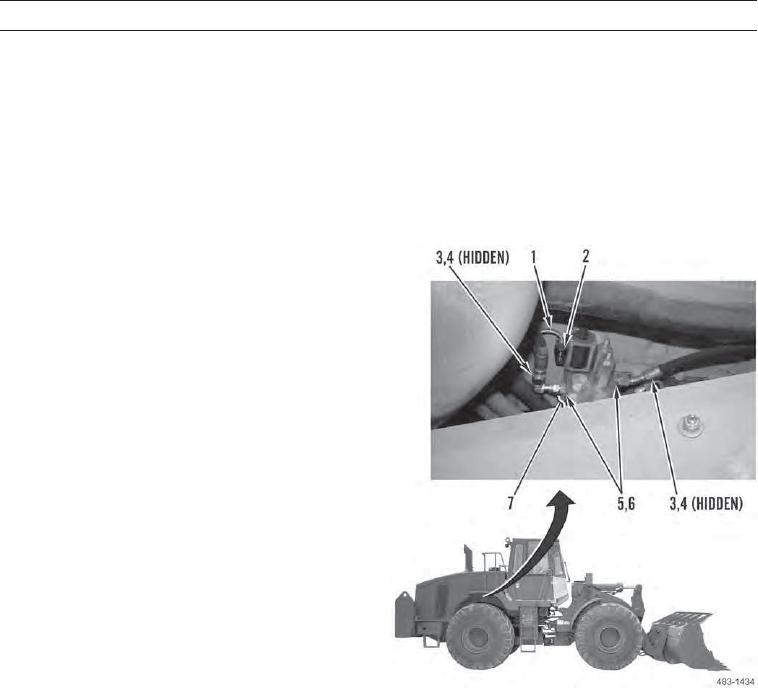
1.
Disconnect engine wiring harness (1) from demand
fan solenoid (2).
2.
Disconnect two hoses (3) and remove O-rings (4)
from fittings (5). Discard O-rings.
3.
Remove two fittings (5) and O-rings (6) from control
manifold (7). Discard O-rings.
0217 00-2