
TM 5-3805-291-23-2
BRAKE CHARGE AND HYDRAULIC FAN CONTROL MANIFOLD REPLACEMENT - CONTINUED
0217 00
REMOVAL - CONTINUED
8.
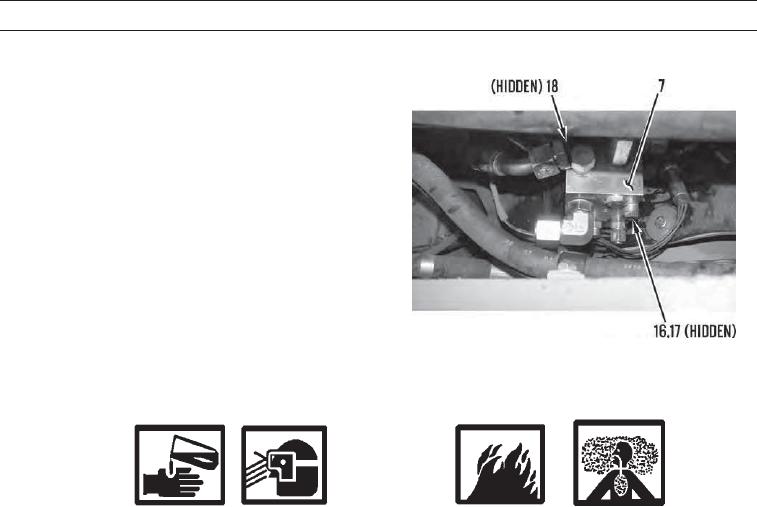
Remove two bolts (16) and spacers (17) from control
manifold (7).
9.
Remove control manifold (7) from engine (18).
427-C1104
INSTALLATION
WARN I N G
Solvent cleaning compound MIL-PRF-680 Type III is an environmentally compliant and low toxic mate-
rial. However, it may be irritating to the eyes and skin. Use protective gloves and goggles. Use in well-venti-
lated areas. Keep away from open flames and other sources of ignition. Failure to do so may result in injury
or death to personnel.
C AU T I O N
Cleanliness is an important factor. Before assembly, all parts should be thoroughly cleaned in cleaning
fluid. Allow the parts to air dry. Wiping cloths or rags should not be used to dry parts. Lint may be depos-
ited on the parts which may cause later trouble. Inspect all parts. If any parts are worn or damaged, use
new parts for replacement.
1.
Position control manifold (7) on engine (18).
2.
Install two spacers (17) and bolts (16) on control manifold (7).
0217 00-4