
TM 5-3805-291-23-2
MAIN HYDRAULIC CONTROL VALVE REPLACEMENT - CONTINUED
0218 00
MAIN HYDRAULIC CONTROL VALVE REMOVAL - CONTINUED
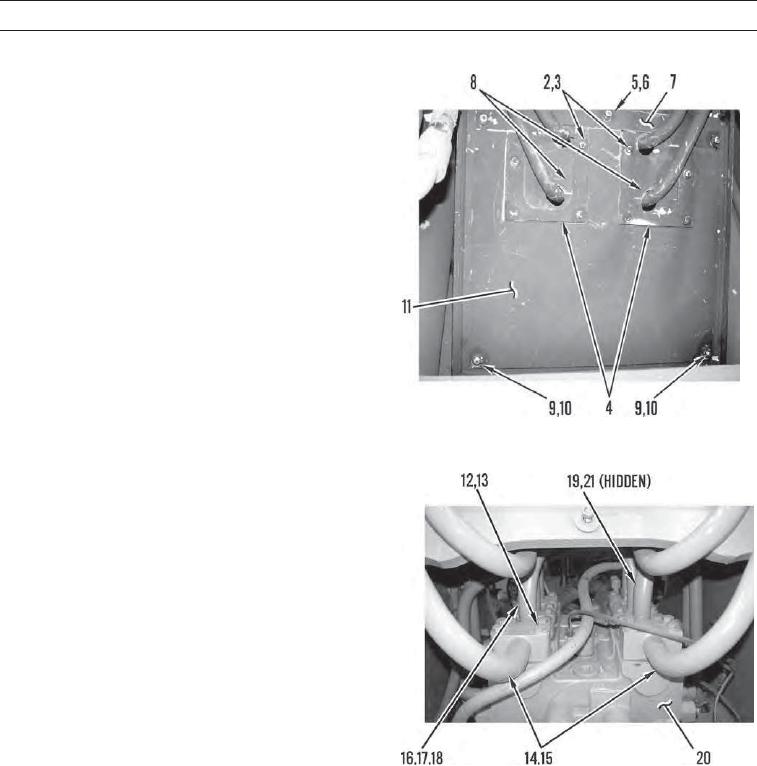
2.
Remove eight bolts (2), washers (3), and two plates
(4) from machine.
3.
Remove three nuts (5), washers (6), and plates (7)
from machine.
4.
Remove two rubber covers (8) from machine.
5.
Remove two nuts (9), washers (10), and cover plate
(11) from machine.
427-C1105
6.
Remove eight bolts (12) and washers (13) from two
tube assemblies (14).
7.
Remove two O-rings (15) from tube assemblies (14).
Discard O-rings.
8.
Remove 24 bolts (16), washers (17), and 12 flange
halves (18) and disconnect eight tube assemblies (19)
from main hydraulic control valve (20).
9.
Remove six O-rings (21) from eight tube assemblies
(19). Discard O-rings.
427-C1106
0218 00-3