
TM 5-3805-292-10
0005
OPERATING MACHINE CONTINUED
Returning Support Strut to Stowed Position
0005
WARNING
Before removing pin, operator must occupy seat. Failure to follow this instruction may
result in death or injury to personnel.
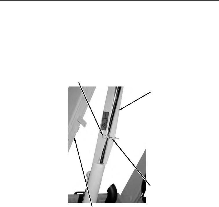
1. Raise loader arms slightly and have assistant unhook retainer (Figure 9, Item 3) and remove pin (Figure 9,
Item 1) from support strut (Figure 9, Item 2). Refer to Operating Machine in this work package.
2. Stow support strut (Figure 9, Item 2) and pin (Figure 9, Item 1) on RH loader arm (Figure 9, Item 4).
3. Lower loader arms (Figure 9, Item 4) to ground. Refer to Operating Machine in this work package.
1
2
3
458-0870
4
Figure 9. Locked Support Strut and Pin.
0005
END OF TASK