
TM 5-3805-292-23
0002
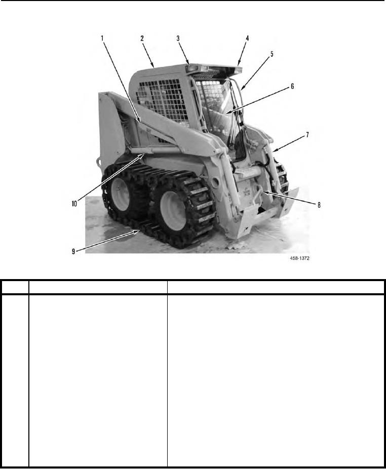
LOCATION AND DESCRIPTION OF MAJOR COMPONENTS CONTINUED
Figure 2. M400W Right-Front 3/4 View.
0002
KEY
COMPONENT
DESCRIPTION
1
Loader Support Strut
Locks loader lift arms in fully raised position when machine is
being serviced.
2
ROPS/FOPS Cab
Protects operator during rollover and from falling objects.
3
Cab Side Lights
Illuminate work area on both sides of machine.
4
Front Work Lights
Illuminate work area to front of machine.
5
Grab Handles
Provide handholds for personnel climbing on machine or tilting
cab structure for service.
6
Windshield
Protects operator from inclement weather and flying objects.
Includes windshield wipers/washers.
7
Tilt Cylinders
Tilt work tool.
8
Tiedowns
Tie machine down during transport.
9
Wheel and Tire Assembly with Steel
Allows machine to operate in rough terrain and increases trac-
Track
tion.
10
Lift Cylinders
Raise and lower loader lift arms.