
TM 5-3805-292-23
0002
LOCATION AND DESCRIPTION OF MAJOR COMPONENTS CONTINUED
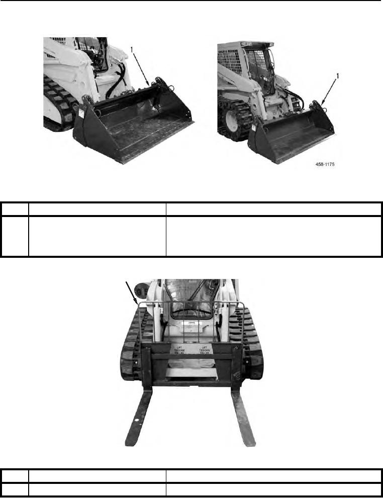
Figure 8. Multi-Purpose Bucket.
0002
KEY
COMPONENT
DESCRIPTION
1
Multi-Purpose Bucket
Has cutting edges and wear plates. Hydraulic cylinder-
activated clamshell jaws open and close to pick up debris
(rocks, tree limbs, etc.). MAXIMUM LOAD: 20 cu-ft for 400T
only. 15 cu-ft for 400W only.
1
458-0848
Figure 9. Pallet Fork.
0002
KEY
COMPONENT
DESCRIPTION
1
Pallet Fork
Allows SSL to function as a forklift.