
TM 5-3805-292-23
0012
A/C COMPRESSOR INSTALLATION CONTINUED
N OT E
Route A/C lines and wiring harnesses as tagged during removal.
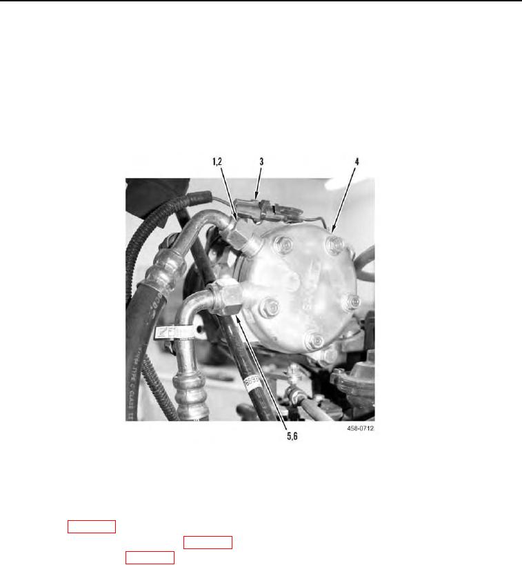
6. Apply refrigerant oil to new O-rings (Figure 5, Items 6 and 2).
7. Install new O-ring (Figure 5, Item 6) and inlet line (Figure 5, Item 5) on A/C compressor (Figure 5, Item 4).
8. Install new O-ring (Figure 5, Item 2) and discharge line (Figure 5, Item 1) on A/C compressor (Figure 5, Item 4).
9. Connect electrical connector (Figure 5, Item 3) to A/C compressor (Figure 5, Item 4).
458-0712
Figure 5. A/C Lines.
0012
END OF TASK
FOLLOW-ON TASKS
00012
1. Install fan (WP 0015).
2. Evacuate and recharge A/C system (WP 0093).
3. Connect battery power (WP 0142).
4. Verify correct operation of machine (TM 5-3805-292-10).
END OF TASK
END OF WORK PACKAGE