
TM 5-3805-292-23
0012
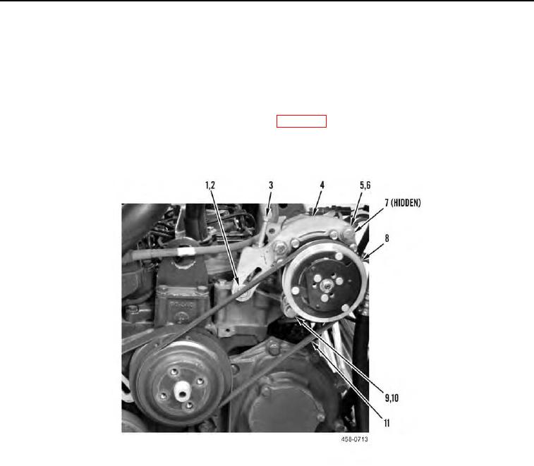
A/C COMPRESSOR REMOVAL CONTINUED
4. Loosen two bolts (Figure 2, Item 9) on A/C compressor (Figure 2, Item 8).
5. Loosen bolt (Figure 2, Item 1) and bolt (Figure 2, Item 3) on bracket (Figure 2, Item 4).
N OT E
Note routing of belt before removal.
6. Remove belt (Figure 2, Item 11) from machine. Refer to WP 0052.
7. Remove bolt (Figure 2, Item 1), washer (Figure 2, Item 2), two bolts (Figure 2, Item 9), washers (Figure 2, Item
10), and A/C compressor (Figure 2, Item 8) from machine.
Figure 2. A/C Compressor and Bracket.
0012
END OF TASK
A/C COMPRESSOR BRACKET REMOVAL
00012
Remove two bolts (Figure 2, Item 5), washers (Figure 2, Item 6), nuts (Figure 2, Item 7), and bracket (Figure 2,
Item 4) from A/C compressor (Figure 2, Item 8).
END OF TASK