
TM 5-3805-292-23
0020
INSTALLATION CONTINUED
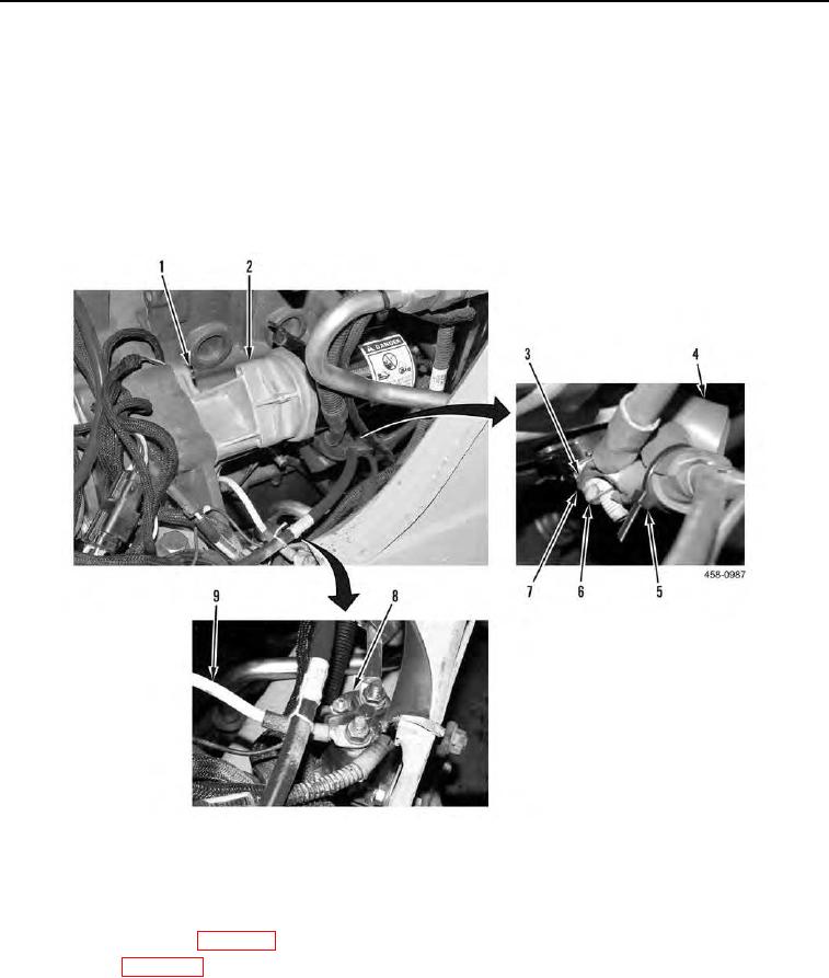
2. Install starter (Figure 4, Item 2) and two bolts (Figure 4, Item 1) on machine.
N OT E
Install cables as tagged during removal.
3. Install two positive cables (Figure 4, Item 3), washer (Figure 4, Item 7), and nut (Figure 4, Item 6) on starter
(Figure 4, Item 2) and position boot (Figure 4, Item 4) over positive cables and install new tiedown strap
(Figure 4, Item 5).
Figure 4. Starter.
0020
END OF TASK
FOLLOW-ON TASKS
00020
1. Connect battery power (WP 0142).
2. Close ROPS (WP 0134).
3. Verify correct operation of machine (TM 5-3805-292-10).
END OF TASK
END OF WORK PACKAGE
0020-5/(6 blank)