
TM 5-3805-292-23
0021
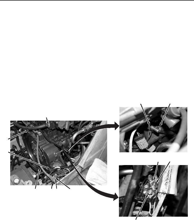
REMOVAL
00021
N OT E
Remove and discard tiedown straps.
Tag all electrical leads.
1. Lift protective cover (Figure 1, Item 11) and remove nut (Figure 1, Item 9), lockwasher (Figure 1, Item 10), and
cable (Figure 1, Item 12) from terminal (Figure 1, Item 8). Discard lockwasher.
2. Disconnect electrical connector (Figure 1, Item 13).
3. Remove nut (Figure 1, Item 2) and engine grounds (Figure 1, Item 3) from engine.
4. Loosen clamp (Figure 1, Item 1) and disconnect heater hose (Figure 1, Item 14) from engine.
N OT E
Note locations of washers to aid in removal.
5. Remove four nuts (Figure 1, Item 5) and three lockwashers (Figure 1, Item 6) and disconnect five wires (Figure
1, Item 4) from two terminals (Figure 1, Item 7). Discard lockwashers.
3
2
1
14
13
4
5,6 (HIDDEN)
8
9,10
11
12
458-1056
7
Figure 1. Engine Hose and Electrical Connections.
0021